Demon Fuel Systems 1920 User Manual
Page 4
4
ADJUSTMENT DATA:
FLOAT LEVEL:
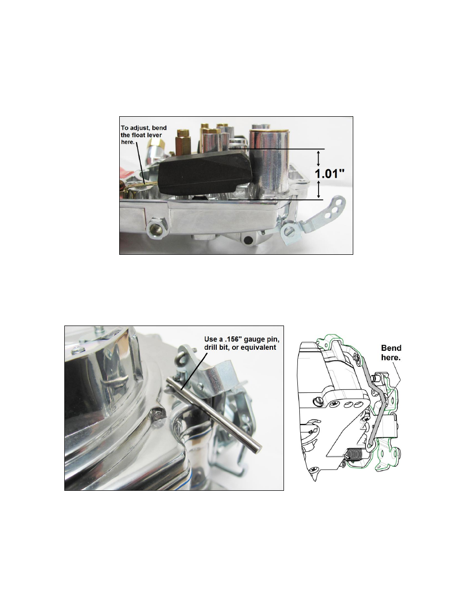
1. With the air horn inverted and weight of float seating needle at the toe of the float, there should be 1.01
” (25.7mm)
between the top of each float and the air horn gasket surface (Fig. 6).
2. To adjust, raise float slightly and bend the float lever. CAUTION! DO NOT PRESS NEEDLE INTO SEAT WHEN
ADJUSTING FLOAT LEVER.
Figure 6
PUMP:
1. Install the pump connector rod in the center hole.
2. Check the clearance (Fig. 7). You may need to bend the pump rod to obtain .15
6” (4.0mm) clearance (Fig. 8).
Figure 7 Figure 8
This manual is related to the following products: