Demon Fuel Systems 1920 User Manual
Page 2
2
DISASSEMBLY:
NOTE: Numbers in parentheses refer to the exploded views in Figures 10 & 11.
1. Remove the choke shaft / lever assembly (5). Remove step up piston cover screws (2) and step-up piston cover
(1). Remove the step up pistons (19), metering rods (15), and springs (14) as an assembly. Metering rods (15)
may be removed from the piston (19), if desired.
2. Remove the pump lever connecting rod (32), c-clips (31), choke connector rod (42), c-clip (31), and cotter pin
(46). Remove the 8 assembly screws (36).
3. Lift the air horn straight up from the fuel bowl to avoid damage to the parts attached. Remove the float pins (8),
floats (9), and fuel needle seat and gasket assembly (20), and strainers (26). Remove the air horn gasket (28).
4. Separate the fuel bowl from the throttle body. Remove the choke cap retainer screws (41), choke cap retainer
(40), choke cap assembly (39), and choke cap gasket (38).
5. Remove the throttle body gasket (34). Set the throttle body (35) and fuel bowl assembly (30) aside for cleaning.
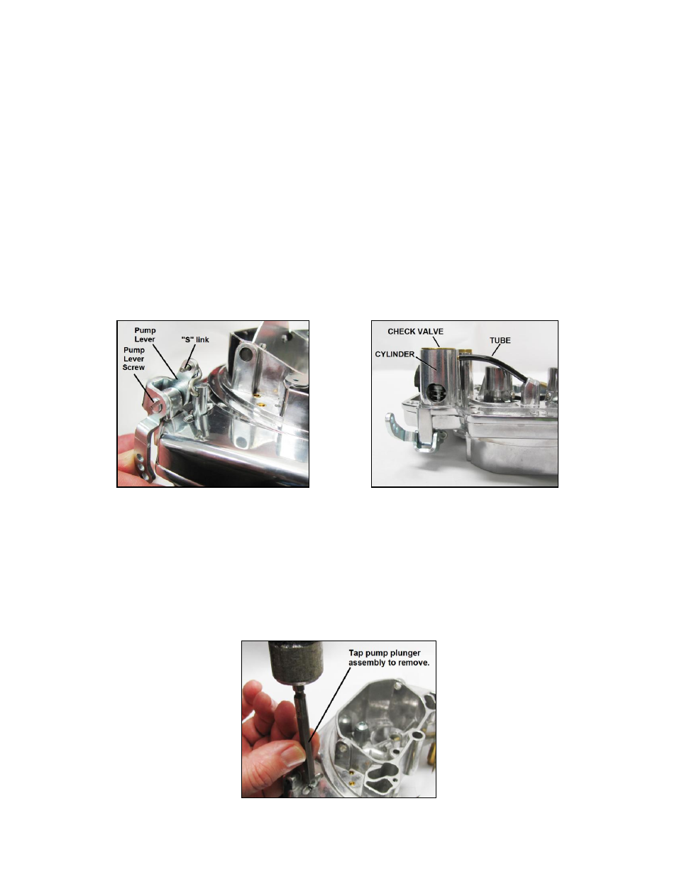
6. Remove the pump lever screw (4), pump lever (3)
, and pump “S” link (21) from the end of the plunger stem (Fig.
1). Remove the fuel inlet fitting (16) and gasket (17).
Figure 1
Figure 2
7. The accelerator pump cylinder is part of the air horn casting and connects to the discharge nozzle in the primary
section through a short flexible tube (Fig. 2). The intake check valve assembly acts as a bottom closure for the
pump cylinder.
8. Remove the accelerator pump intake check valve (12) and accelerator pump assembly (10). The accelerator
pump intake check valve fits tightly into the bottom of the accelerator pump cylinder and can be removed by
tapping lightly on the end of the pump plunger shaft. Tap the end of accelerator pump plunger carefully to guard
against damage to the shaft or the air horn assembly (Fig. 3). Once the accelerator intake check valve is
removed, carefully pull the accelerator pump assembly from the air horn.
Figure 3