Demon Fuel Systems 1920 User Manual
Page 3
3
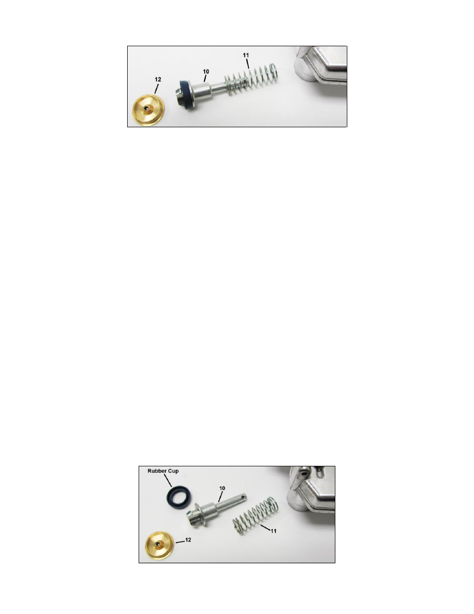
9. Remove the accelerator pump plunger assembly (10) and spring (11). See Fig. 4.
Figure 4
10. Remove the rubber cup from the pump plunger assembly.
11. Remove the primary (6) and secondary jets (13), noting their locations.
12. Remove the discharge nozzle screw (23), discharge nozzle (22), and discharge nozzle gaskets (24). Invert the air
horn to remove discharge check needle (25).
13. Remove the idle mixture screws (47) and springs (48) from the throttle body assembly (35). Remove any rubber
vacuum caps at this time.
CLEANING:
Clean all parts thoroughly in an approved cleaning solvent or lacquer thinner. Special attention should be given to carbon
deposits in throttle bores and passages. Do not use wires or pointed tools to clean passages and calibrated holes as
calibration of carburetor may be destroyed. Do not immerse rubber or similar materials in cleaning solvent.
REASSEMBLY:
Reverse the disassembly sequence. Note the following special instructions:
1. To ensure proper usage of gaskets and parts packaged in kit, use old gaskets and parts for identification.
2. Idle mixture screws should be seated lightly and then backed out approximately 1-1/2 to 2 turns for initial setting.
3. Install the new accelerator pump rubber cup on the pump plunger assembly (10). See Fig. 5.
4. Push the accelerator pump stem into the accelerator pump cylinder to compress the spring. Install the new brass
accelerator pump intake check valve. Avoid contact with the check valve orifice area during assembly. Install
open end of “S” link in pump shaft toward choke valve.
5. Refer to Adjustment Data for adjustment specification (Fig. 6 & 7).
6. When installing the choke cap, be sure the pick-up lever (in the housing) fits into the loop on the bi-metal spring.
Proper assembly may be verified by turning the choke cap in both directions. The choke plate should open when
rotated clockwise, and it should close when rotated counter-clockwise.
Figure 5