American Fibertek MRX-986C-SL User Manual
Page 6
6
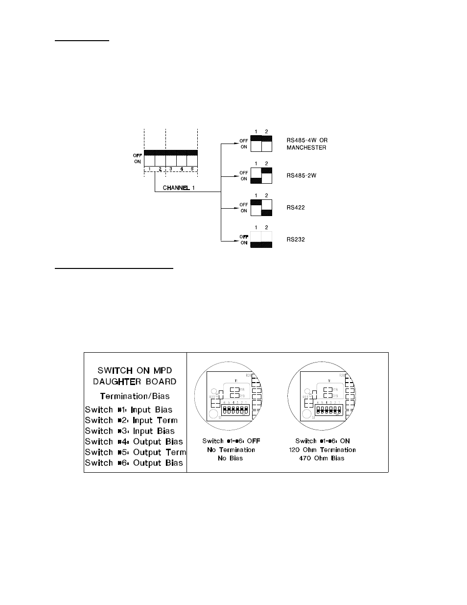
DATA MODE
NOTE: This unit is shipped with Data Channel 1 in the RS485 4-wire configuration and
Data Channel 2 in a Contact Closure configuration.
For other configurations of data channel 1 please refer to the drawing below for changes to the
default switch settings. The configuration switch is located on the rear of the unit (next to the
video BNC connectors) and can be modified without opening the unit. Please note that switch #
3, 4, and 5 are not used and should remain in the off (up) position. Switch # 3, 4, and 5 must
also remain in the off (up) position for proper contact closure operation.
DATA TERMINATION / BIAS
NOTE: This unit is shipped with Data Termination and Bias switches in the off position.
Switches are available inside the unit that allow termination and offset bias features to be
activated. These switches rarely near to be changed from the default settings. The drawing
below illustrates the function of each of these switches. To gain access to these switches
remove the top cover of the MTX-986C-SL and the MRX-986C-SL by removing the fourteen
screws joining the cover to the main housing. This switch bank is located on the plug-in PCB
behind the data mode switch bank.
.