American Fibertek MRX-986C-SL User Manual
Page 5
5
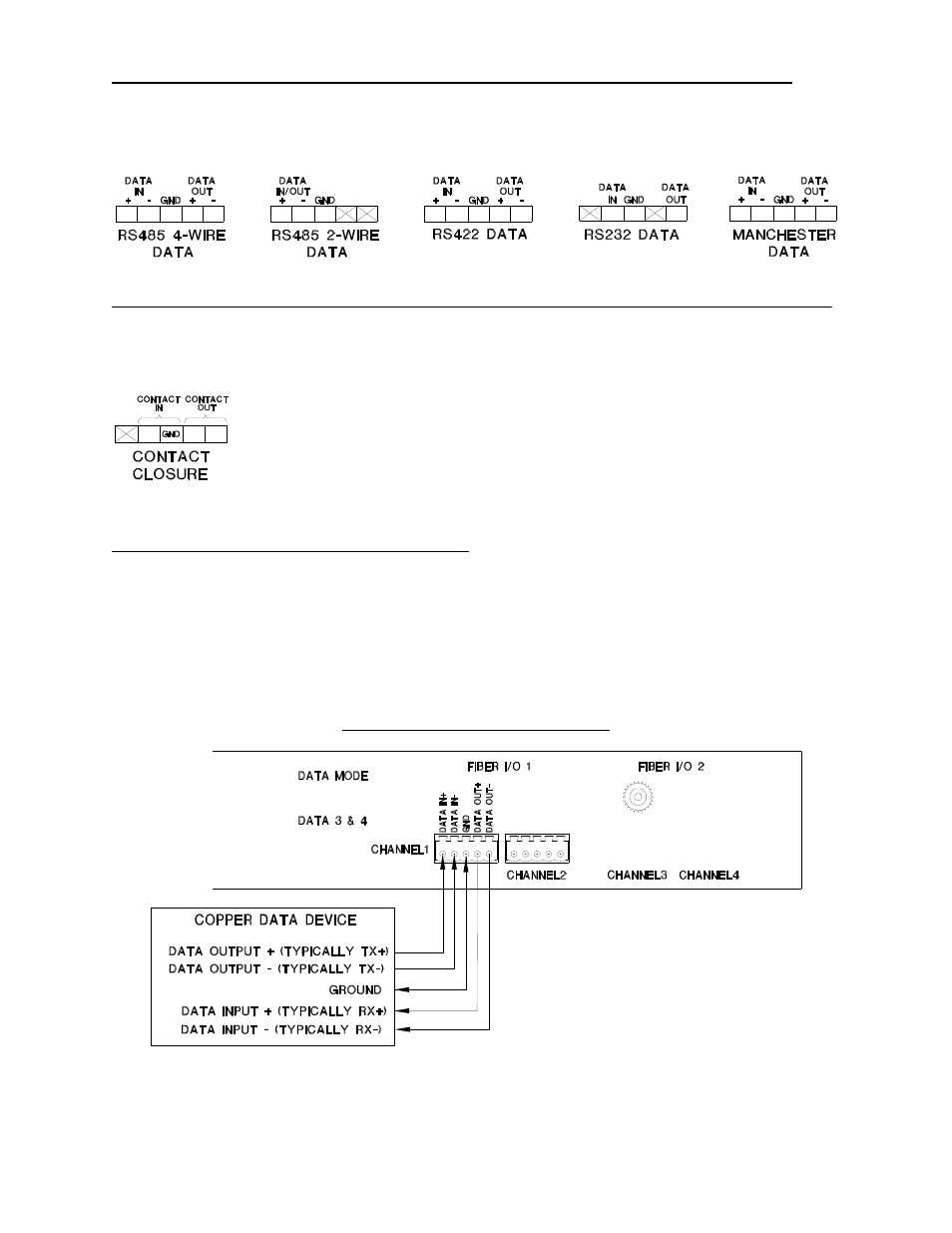
MTX-986C-SL/MRX-986C-SL DATA INPUT / OUTPUT CONNECTIONS (DATA 1)
Data input and output connections are made via terminal blocks on the back of the unit. See the
drawings below for proper orientation of the input and output connections. Please note that the
far right pin on each connection drawing corresponds with the far right terminal block pin on the
unit.
MTX-986C-SL/MRX-986C-SL CONTACT INPUT / OUTPUT CONNECTIONS (DATA 2)
Data input and output connections are made via terminal blocks on the back of the unit. See the
drawing below for proper orientation of the input and output connections. Please note that the
far right pin on the connection drawing corresponds with the far right terminal block pin on the
unit.
TYPICAL SYSTEM DATA CONNECTIONS
An example of the RS422 or RS485 four wire interconnection between the 986C-SL series unit
and the copper device to which it is attached is shown below. This illustration is based on
industry standard EIA terminology for the transmission of electronic data signals. Using this
terminology, the driver of an electronic signal is labeled TX or data out. Correspondingly, the
receiver of an electronic signal is labeled RX or data in. Not all manufactures follow standard
EIA terminology. Consult the installation instructions for your copper device if you are unsure
which two wires are the drive (data out) wires and which two wires are the receive (data in)
wires.
MTX-986C-SL or MRX-986C-SL
Please note that Data In on the MTX-986C-SL becomes Data Out on the MRX-986C-SL after
going across the fiber. The reverse flow follows the same orientation.