American Fibertek MRX-91685C-SL User Manual
Page 5
5
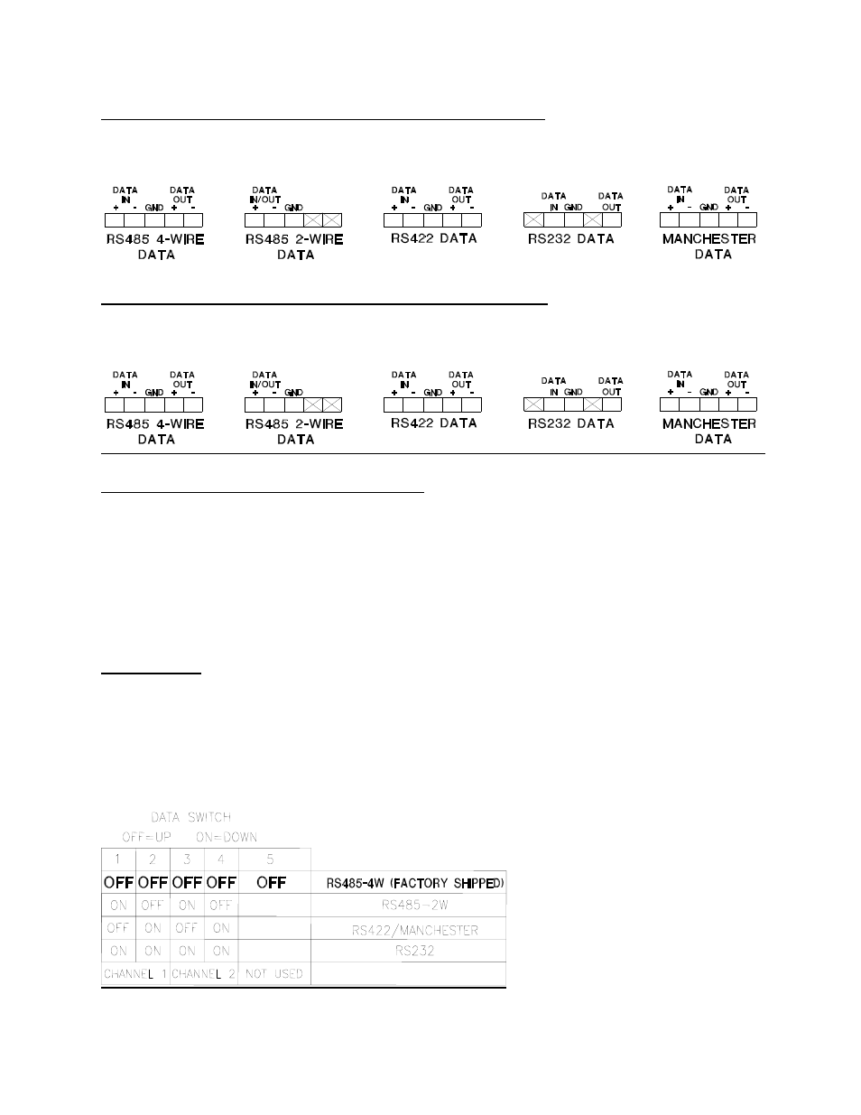
MTX-91685C-SL DATA INPUT / OUTPUT CONNECTIONS
Data input and output connections are made via terminal blocks on the back of the unit. See the
drawings below for proper orientation of the input and output connections for each of the two
data channels.
MRX-91685C-SL DATA INPUT / OUTPUT CONNECTIONS
Data input and output connections are made via terminal blocks on the back of the unit. See the
drawings below for proper orientation of the input and output connections for each of the two
data channels.
TYPICAL SYSTEM DATA CONNECTIONS
The connection terminology is based on industry standard EIA terminology for the transmission
of electronic data signals. Using this terminology, the driver of an electronic signal is labeled TX
or data out. Correspondingly, the receiver of an electronic signal is labeled RX or data in. Not all
manufactures follow standard EIA terminology. Consult the installation instructions for your
copper device if you are unsure which two wires are the drive (data out) wires and which two
wires are the receive (data in) wires. Please note that Data In on the MTX-91685C-SL becomes
Data Out on the MRX-91685C-SL after going across the fiber. The reverse flow follows the
same orientation.
DATA MODE
NOTE: This unit shipped with Data Mode switches in the RS485 4-wire position.
For other configurations of data channel 1 or data channel 2, please refer to the drawing below
for changes to the default switch settings. These configuration switches are located on the front
of the unit and can be modified without opening the unit. Please note that switch # 1 and switch
# 2 are not used and should remain in the off (up) position.