American Fibertek MRX-91685C-SL User Manual
Page 4
4
To install the MTX-91685C-SL or MRX-91685C-SL it is first necessary to mount the rack flanges
to the unit.
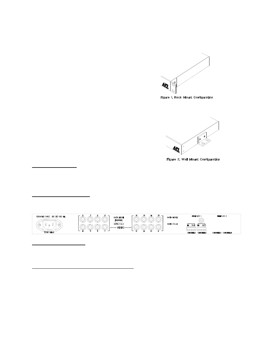
For rack mounting the ears are installed on the
sides of the unit with the surfaces that have
oval holes flush with the front of the unit as in
Figure 1. Mount the ears with the #10 flathead
screws provided. To mount in the rack cabinet,
use mounting screws that are appropriate for
the rack cabinet being used. When mounting
the MTX-91685C-SL or MRX-91685C-SL in a
rack configuration, it is recommended that
sufficient airflow is available through the unit.
This can be achieved by leaving a 1RU slot above the unit open for air movement and by
leaving open space along the sides of the unit.
For mounting the unit flush to a wall or other rigid
surface, the ears may be installed on the sides
with the oval holes flush with the bottom of the unit
as in Figure 2. Mount the ears with the #10
flathead screws provided. Mount the unit to a rigid
surface using #10 (5mm) screws.
POWER SOURCE
The internal power supply accepts universal line voltage. Any mains supply from 100 to 240
VAC, 50 to 60 Hz, may be used without modification or adjustment. A universal power
connector is provided on the rear of the unit to facilitate connection to the power mains.
POWER CONNECTION
The unit is supplied with a three conductor power cord (US, UK, or Euro). The “ground”
conductor is directly connected to the chassis.
FIBER CONNECTION
The fiber optic connection is made via a FC connector located at the back of the unit. Be sure to
allow sufficient room for the required minimum bend radius of the fiber cable used.
VIDEO INPUT / OUTPUT CONNECTIONS
Video input and output connections are located on the rear of the unit. A BNC connector is
provided for each channel. The video inputs are connected to an appropriate 75
baseband
video source such as a camera or a video recorder output. The 75
video outputs can be
looped through typical baseband video inputs of switchers, recorders and other equipment as
required. For proper operation, the outputs must be terminated with 75
. For optimum
performance the video cables should be the shortest length of coax practical.