3 motherboard layout, 4 layout contents, Motherboard layout -7 – Asus M3A78 User Manual
Page 17: Layout contents -7, 3 motherboard layout 1.5.4 layout contents, Chapter 1: product introduction 1-7
1.5.3
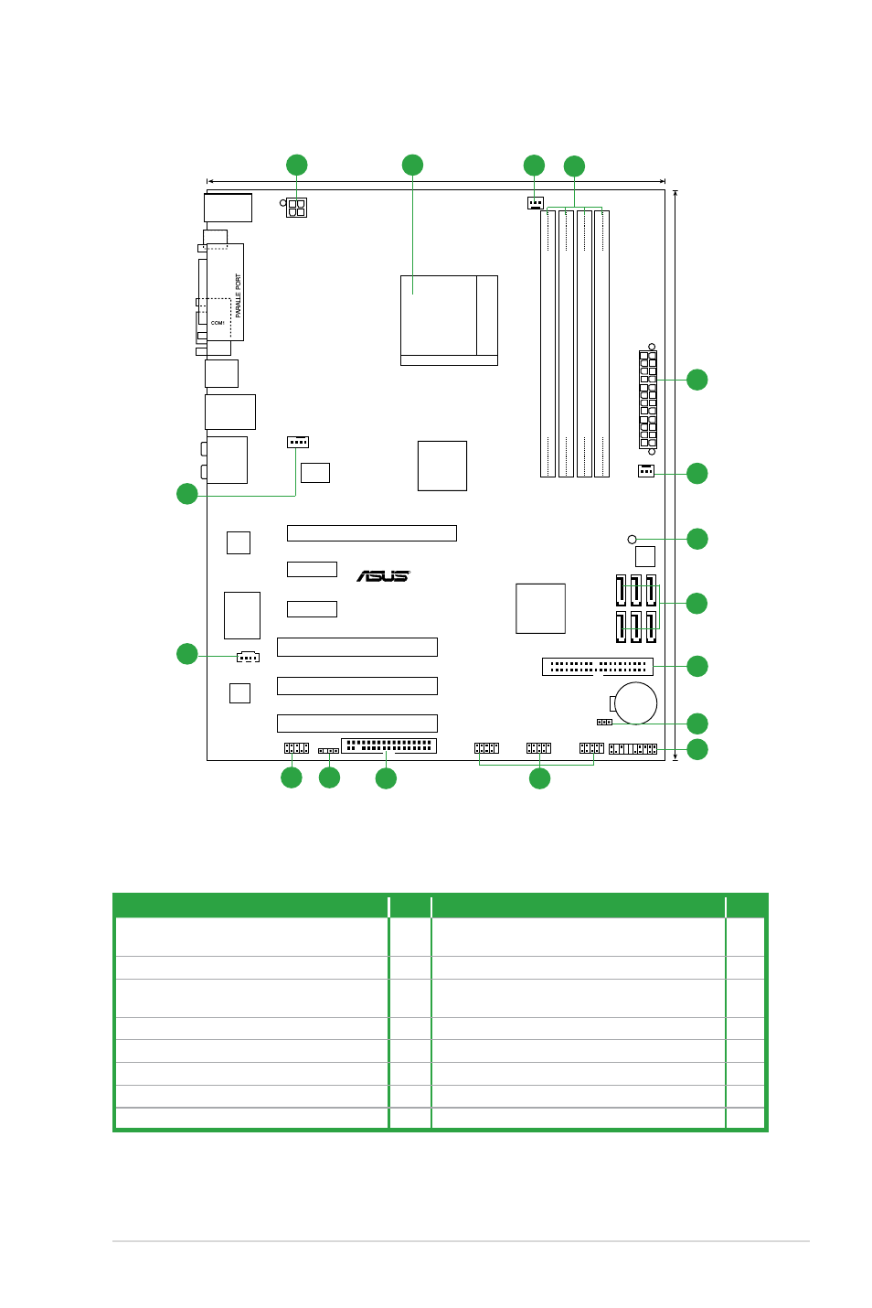
Motherboard layout
1.5.4
Layout contents
Super I/O
SATA4 SATA5 SATA6
SATA1 SATA2 SATA3
SocketAM2+
CPU_FAN
EA
TXPW
R
PANEL
USB78
USB910
USB1112
AAFP
SB_PWR
8Mb
BIOS
AMD 770
SB700
DDR2 DIMM_A1 (64 bit,240-pin module)
DDR2 DIMM_B1 (64 bit,240-pin module)
DDR2 DIMM_A2 (64 bit,240-pin module)
DDR2 DIMM_B2 (64 bit,240-pin module)
CR2032 3V
Lithium Cell
CMOS Power
PCI2
PCI3
PCI1
PCIEX16
PCIEX1_2
PCIEX1_1
CLRTC
ATX12V
R
SPDIF_OUT
M3A78
FLOPPY
CD
30.5cm (12in
)
VIA
VT1708B
PRI_IDE
24.4cm(9.6in)
KB_USB56
PWR_FAN
CHA_FAN
RTL
8111C
RTM
880T-792
AUDIO
LAN1_USB12
USB34
SPDOF_O
1
2
3
4
1
5
8
9
10
6
15
16
7
12
13
14
11
Connectors/Jumpers/Slots
Page Connectors/Jumpers/Slots
Page
1.
ATX power connectors
(24-pin EATXPWR, 4-pin ATX12V)
1-21 10. Clear RTC RAM (CLRTC)
1-17
2.
AM2/AM2+ CPU socket
1-8
10. System panel connector (20-8 pin PANEL)
1-23
3.
Chassis fan connector (3-pin CHA_FAN)
1-9
11. USB connectors (10-1 pin USB78, USB910,
USB1112)
1-24
4.
DDR2 DIMM slots
1-11
12. Floppy disk drive connector (34-1 pin FLOPPY) 1-19
5.
Power fan connector (3-pin PWR_FAN)
1-24 13. Digital audio connector (4-1 pin SPDIF_OUT)
1-23
6.
Serial ATA connectors (7-pin SATA1-6)
1-22 14. Front panel audio connector (10-1 pin AAFP)
1-25
7.
Onboard LED
1-5
15. Optical drive audio connector (4-pin CD)
1-22
8.
IDE connector (40-1 pin PRI_IDE)
1-20 16. CPU fan connector (4-pin CPU_FAN)
1-9
Chapter 1: Product introduction
1-7