Installing and removing xfp module, Installing xfp module – AB Soft SigmaBlade N8406-026 User Manual
Page 54
(English)
32
Installing and Removing XFP Module
The following is described how to install and remove N8406-027 10GbE XFP Module in and from N8406-026 10Gb
Intelligent L3 Switch.
IMPORTANT:
Attach the dust covers to all vacant LC connectors to protect them
from contamination, if you store or transport the Switch Module
which the XFP modules are installed.
Optical power and sensitivity may be lower and cause malfunction
by coming into contact with contamination.
Install the XFP module to the XFP module slot straight. Do not force
to install it to avoid damage the module.
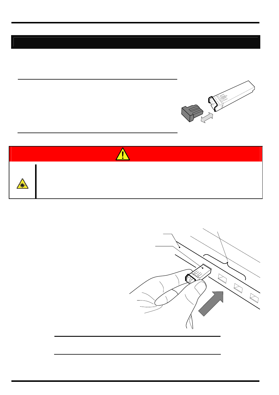
Dust cover
XFP Module
Avoid direct look into the laser beam.
The N8406-027 10GbE XFP Module is classified as a Class 1 Laser Product. A class 1
laser will not be harmful to the human body. However, do not look directly into the XFP
module port during operation. Keep any vacant LC connector covered with a dust cover
(rubber cap) when you do not use it or you transport it.
Installing XFP Module
Remove the dust cover attached to the XFP module.
Insert the XFP module to the XFP
module slot in the Switch Module.
NOTE:
Insert the XFP module to the XFP module slot without pulling
down the lever. If you insert with the lever pulled down, a communication
failure may occur.
WARNING