Installation – Alliance Laundry Systems UVN255P User Manual
Page 27
Cod. G522433
© Copyright 2009, Alliance Laundry System LLC – DO NOT COPY OR TRANSMIT Rev. 00/0510
Installation
27
RELAY CONTACTS POWERED FROM THE WASHER
CONTROL CIRCUIT
Use of four dosing signals
The dosing signals from 1 to 4 originate from the board.
Supply terminal COM from terminal X0-A of A4 board.
(cable not supplied) fig. 23.
Supply common phase of the signal outputs from terminal
X0-B of A4board.
Dosing outputs: connect in the order mentioned in the table
in section 3.6.2.
IMPORTANT
This connection allows for the maximum strength at
each of the 50mA outputs. Higher consumption can
prevent the washer from functioning correctly.
This connection can aggravate any problems produced
by a fault in the grounding connection, both of the
washer itself and of the external dosing equipment.
fig. 23
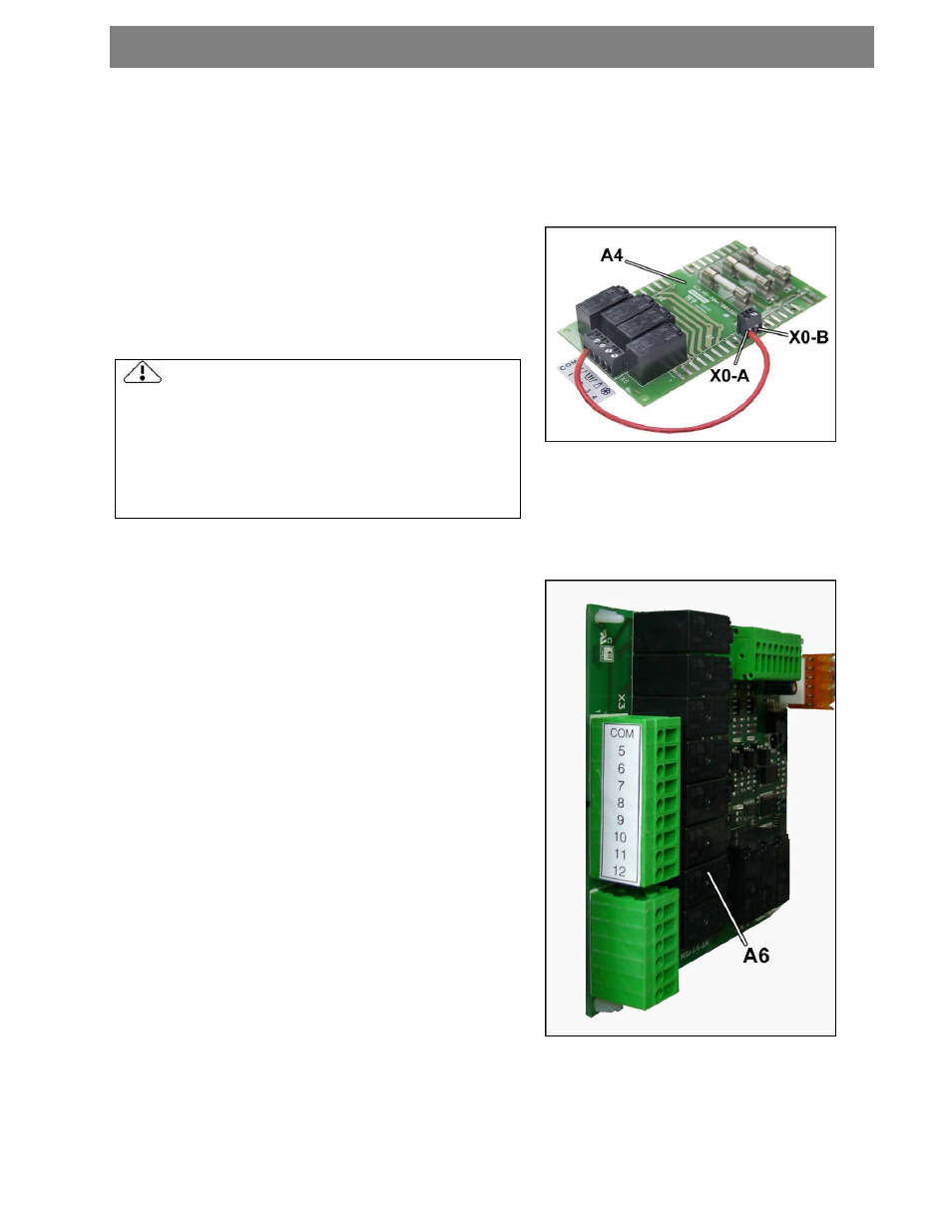
USE OF MORE THAN FOUR DOSING SIGNALS
Applicable in both options, for dry contacts or relay
contacts supplied from the machine itself.
The dosing signals from 5 to 12 are originated in A6 board
(fig. 24)
Supply terminal COM of A6 board from terminal X0-A of A4
board (cable not supplied).
Dosing outputs: connect in the order mentioned in the table
in section 3.6.2.
fig. 24