Installation instructions for gas conversion, 5 change griddle orifice, 6a change main bake burner orifice – GE ZGP304NRSS User Manual
Page 24
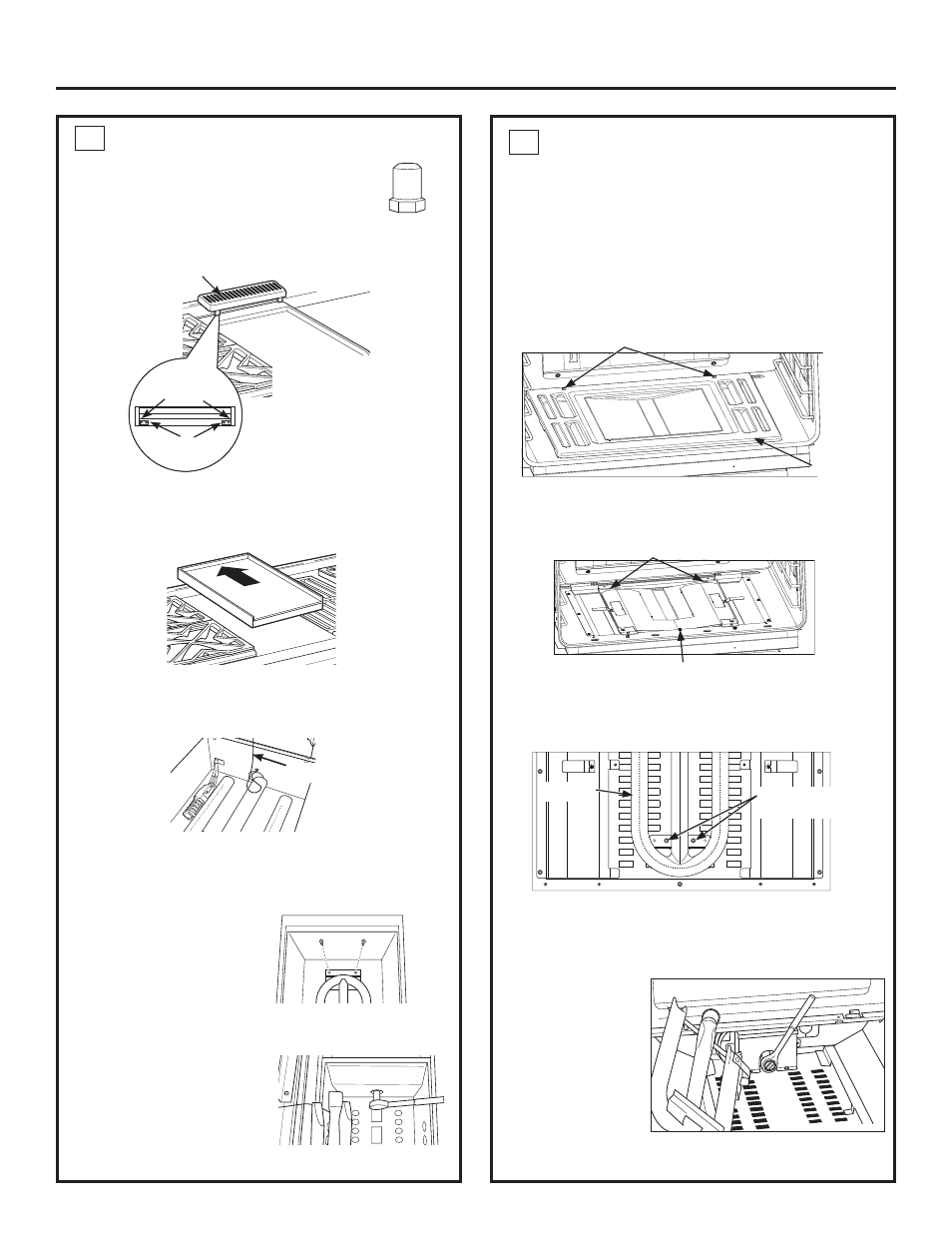
5 CHANGE GRIDDLE ORIFICE
(if present)
Locate the 3/4” long griddle orifice.
Select the proper orifice size for your gas and
burner from the conversion chart.
A. Lift off the griddle flue cover. Remove the 2 inside
clamping screws.
B. Lift out the cast-iron grease trough. Slide the
griddle toward the rear and out of the hold-down
tabs along the bottom.
C. Carefully lift and hold the griddle while pulling
additional length of the capillary from the entry
hole. Stand the griddle on end in the grease sump.
D. Remove the 2 hold-down screws at the rear of the
burner.
Pull the burner straight back toward the rear and
out of the gas inlet.
E. Use a 1/2” deepwell socket to remove and replace
the orifice.
Reverse these steps to
reassemble the griddle.
Push excess capillary
back into the entry hole.
Place the unused orifice
in the holder for possible
future use.
6A CHANGE MAIN BAKE BURNER
ORIFICE
Locate the 3/4” long bake burner orifice.
Select the proper orifice size for your gas and burner from
the conversion chart.
A. Remove the oven door and set aside in a safe
location.
B. Remove the 2 oven bottom hold-down screws
from the rear of the cover.
C. Slide the oven bottom forward and set aside.
D. Remove the burner diffuser screw.
E.
Lift the front of the burner diffuser up slightly and
slide it forward to disengage the clips at the rear.
Set the burner diffuser aside.
F. Remove the 2 burner retention screws.
G. Lift the front of the burner up slightly and slide
forward setting aside (careful not to damage the
igniter.)
H. Use a 1/2”
deepwell socket
to remove and
replace the
orifice.
I. Reverse
these
steps to
reassemble the
oven burner and oven parts. Place the unused
orifice in the holder for possible future use.
24
Installation Instructions for Gas Conversion
Capillary
Front of Range
Back of Range
Griddle Flue Cover
Clamping
Screws
Leveling Screws
NOTE: Remove
the 2 screws
positioned on
the inside only.
Do not remove
the outermost
VFUHZV³
they are for
leveling.
Burner retention
screws
Burner
Diffuser screw
Clips
Hold-Down Screws
Oven
Bottom