Installation instructions, Mark holes, Choose venting option – GE JV536HSS User Manual
Page 13: A. outside top exhaust (vertical duct–3, X 10, Rectangular), B. outside top exhaust (vertical duct–7, Round), Iru-96hulhvprghovrqo, C. outside rear exhaust (horizontal duct–3
13
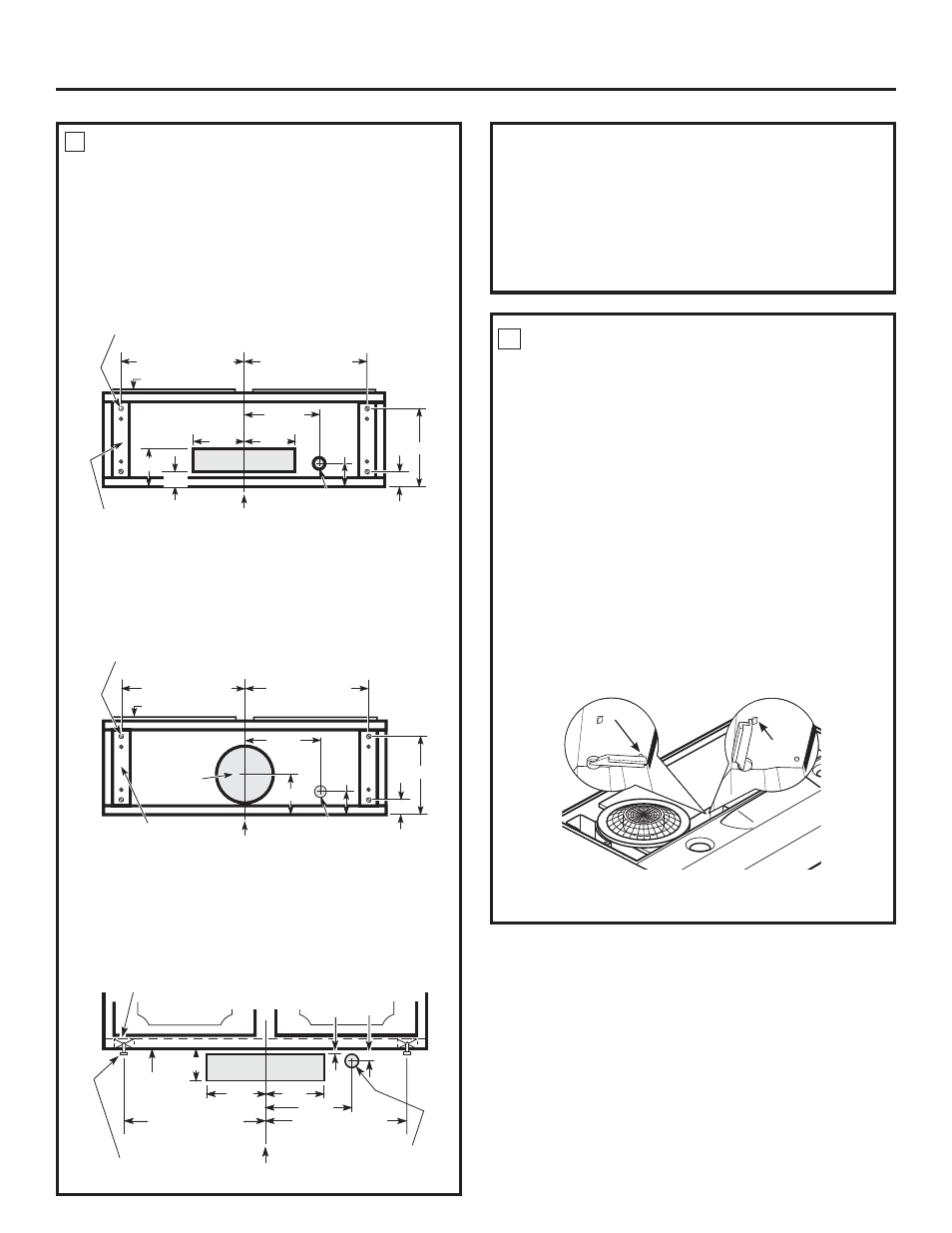
MARK HOLES
Select the vent option that your installation will require
DQGSURFHHGWRWKDWVHFWLRQ
Hood mounting screws (4)
13
15
ø
16
” (30” hood)
16
15
ø
16
” (36” hood)
13
15
ø
16
” (30” hood)
16
15
ø
16
” (36” hood)
Cabinet front
Center
line
Electrical
access hole (in
cabinet bottom)
Wood shims
(recessed-bottom
cabinets only)
Vertical duct
access hole
10
1
ш
2
”
1
1
ш
4
”
2”
12
9
ш
16
”
5”
1
1
ш
4
”
A. Outside top exhaust
(Vertical duct–3
1
ø
4
”
x 10
”
Rectangular)
• Use the diagram or the hood as a template and mark
the locations on the cabinet for ductwork, electrical
wiring and keyhole screw slots.
B. Outside top exhaust (Vertical duct–7
”
Round)
• Use the diagram or the hood as a template and
mark the locations on the cabinet for ductwork,
electrical wiring and keyhole screw slots.
Hood mounting screws (4)
13
15
ø
16
” (30” hood)
16
15
ø
16
” (36” hood)
13
15
ø
16
” (30” hood)
16
15
ø
16
” (36” hood)
Cabinet front
Center line
Electrical access hole
(in cabinet bottom)
Wood shims (recessed-
bottom cabinets only)
Access
KROHIRU”
round duct
10
1
ш
2
”
1
1
ш
2
”
1
1
ш
4
”
12
1
ш
2
”
5”
Cabinet bottom
8
”
DIA.
HOLE
CHOOSE VENTING OPTION
(IRU-96HULHVPRGHOVRQO\
Cabinet Bottom
9
10
Wood shims (recessed-bottom cabinets only)
Cabinet front
Center line
Electrical access hole
(in wall)
Hood mounting screws (4)
Horizontal duct
access hole
Cabinet
bottom
13
15
ø
16
” (30” hood)
16
15
ø
16
” (36” hood)
1
ш
16
”
1
ш
8
”
3
3
ш
4
”
5
1
ш
4
”
5
1
ш
4
”
12
ш
16
”
13
15
ш
16
” (30” hood)
16
15
ø
16
” (36” hood)
C. Outside rear exhaust
(Horizontal duct–3
1
ø
4
”
x 10
”
Rectangular)
• Use the diagram or the hood as a template and
mark the locations on the cabinet for ductwork,
electrical wiring and keyhole screw slots.
D. Recirculating (non-vented ductless–
$YDLODEOHRQ-96HULHVPRGHOVRQO\
• Use the hood as a template and mark the locations
on the cabinet for the electrical wiring and keyhole
screw slots.
• Since the hood is to be recirculated (not to be vented
outside), do not cut out any vent openings in the wall or
cabinet bottom.
The hood can be set to vent outside or to recirculate air
back into the kitchen.
The plastic vent lever is located near the center of the
hood opening.
•
To vent to the outside, make sure the plastic vent
lever is in the HORIZONTAL position (flat against the
metal top of the hood).
•
To recirculate air into the kitchen, make sure the
plastic vent lever is in the VERTICAL position
(flat against the plastic blower housing).
NOTE: In order to change the vent lever position,
you will need to pull the lever out slightly to clear the
plastic tabs.
5
1
ш
4
”
5
1
ш
4
”
Installation Instructions
Set for
outside venting
Set for
recirculating
Stop tab
Hood shown lying upside down
Stop tab