Installation, Continued – Alpine DVA-9965E User Manual
Page 65
63
-EN
Installation
Accessory List
• Head unit ........................................................................ 1
• Power Supply box .......................................................... 1
• Power cable .................................................................... 1
• S video cable .................................................................. 1
• RCA extension cable (for video signal) ....................... 1
• Mounting sleeve ............................................................. 1
• Screw (M5
× 8) ................................................................ 4
• Flange-head tapping screw (M4
× 14) .......................... 4
• Velcro Fasteners ............................................................ 2
• Front frame ..................................................................... 1
• Remote Control .............................................................. 1
• Battery (CR2025) ............................................................ 1
• Carrying case ................................................................. 1
• Owner's Manual ...................................................... 1 set
Caution
When you install this unit in your car, do not remove the detachable
front panel.
If the detachable front panel is removed during installation, you
might press too hard and warp the metal plate that holds it in place.
1
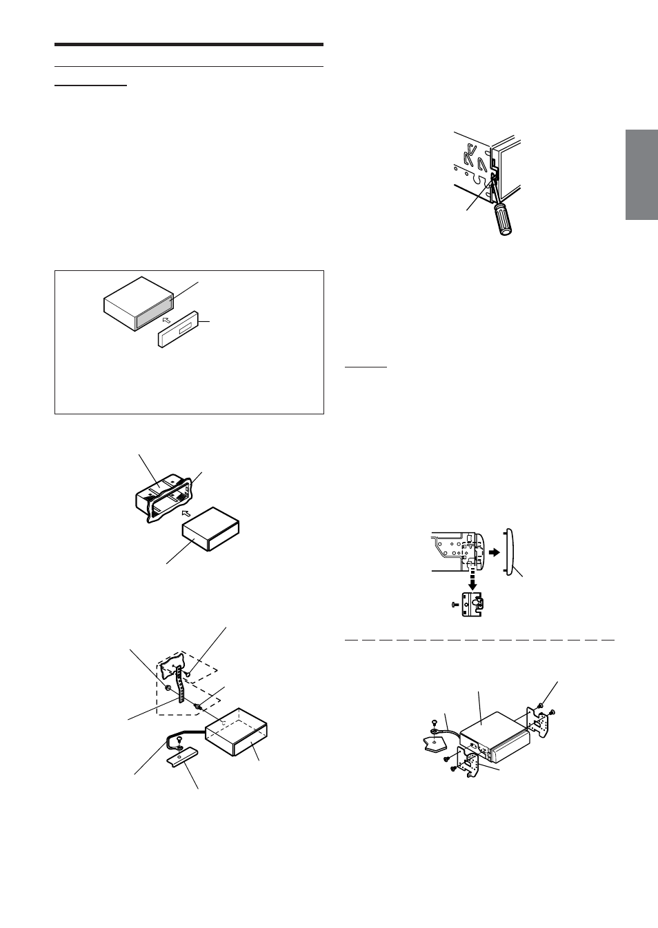
Slide the mounting sleeve into the dashboard.
2
Reinforce the head unit with the metal mounting
strap (not supplied). Secure the ground lead of the
unit to a clean metal spot using a screw (*
1
) already
attached to the vehicle’s chassis.
• For the screw marked “*
2
”, use an appropriate screw for the
chosen mounting location.
Metal plate
Detachable
Front panel
Connect each input lead coming from an amplifier
or equalizer to the corresponding output lead
coming from the left rear of the DVA-9965E.
Connect all other leads of the DVA-9965E
according to details described in the
CONNECTlONS section.
3
Slide the DVA-9965E into the dashboard. When the
unit is in place, make sure the locking pins are fully
seated in the down position. This can be done by
pressing firmly in on the unit while pushing the
locking pin down with a small screwdriver. This
ensures that the unit is properly locked and will not
accidentally come out from the dashboard. Install
the detachable front panel.
Removal
1 Remove the detachable front panel.
2 Use a small screwdriver (or similar tool) to push the
locking pins to the “up” position (see above drawing).
As each pin is unlocked, gently pull out on the unit to
make sure it does not re-lock before unlocking the
second pin.
3 Pull the unit out, keeping it unlocked as you do so.
Front Frame
• Secure the ground lead of the unit to a clean metal spot using a
screw (*
3
) already attached to the vehicle's chassis.
Lock Pin
Mounting Bracket
Ground Lead
Screws (M5
× 8)
(Included)
*
3
this unit
Continued
Metal
Mounting
Strap
Chassis
Hex Nut (M5)
Bolt Stud
Ground Lead
*
2
*
1
Screw
this unit
Mounting Sleeve
(Included)
Dashboard
this unit