Figure 1 – APW Wyott XWAV1829 User Manual
Page 5
5
Warning
Caution
Warning:
Warning:
:
Ensure that operation location is at a reasonable distance from combustible walls and materials
otherwise combustion or discoloration could occur.
:
Place unit on a stable, level counter at a convenient height for use. Turn the adjustable feet so
that unit is level to countertop. The top of the unit is not intended for use a shelf. Materials
placed there are at risk for fire.
8. Before plugging unit into wall, make sure that the switch is in the off position.
9.
Ensure no hands, tools or parts or other unintended items are located on the conveyor
as injury will result when unit is turned on.
10. Plug unit into grounded electrical outlet with correct voltage, and plug configuration.
Using any receptacle that is not designed to match the attached cord and plug
cause
personal injury and
void your warranty.
Operating environment
Operating environment
Stand-off/Air-divider located on rear panel is
important in maintaining proper division of inlet and exhaust air flow - If removed it could result in
improper functioning of unit and
cause personal injury and
void your warranty.
Please attach the XWAV1422/Medium Size unit,
208V, 5400W only, to an individual branch circuit.
MAY
WILL
MAY
WILL
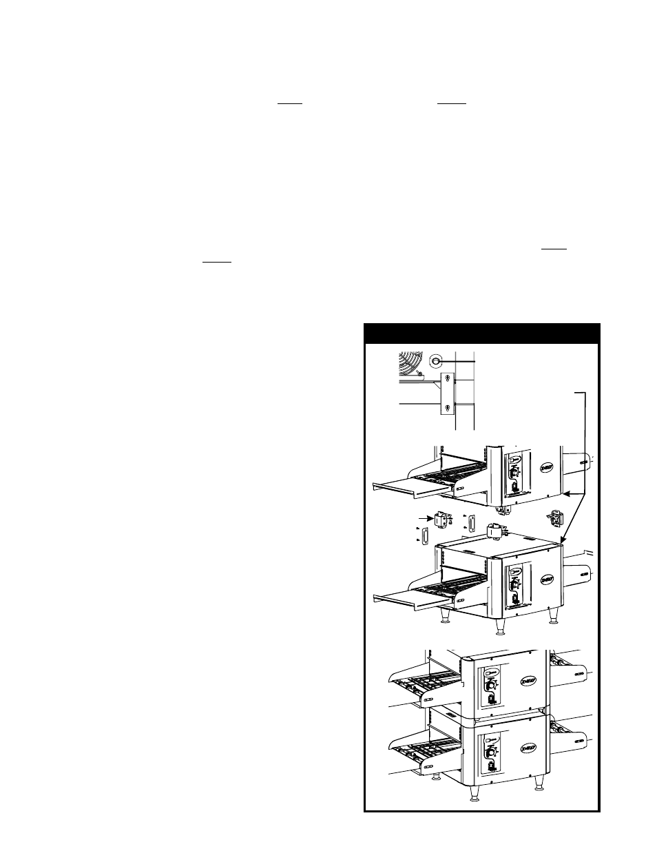
Oven Stacking
Warning:
Warning:
Warning:
The stacking kit will consist of 4 corner posts to be inserted
between stacked units.
When stacking, unit must have proper
stacking kit installed. This will prevent overheating
and damaging of electrical components.
Do not stack more than three units tall or do
not use more than two stacking kits.
Standoff on rear panel of unit is important to
allow proper inlet and exhaust fan airflow. Do not
cover inlet or exhaust fan openings as this could
damage electrical components.
1. Ensure bottom unit is mounted on secure
surface, with feet installed.
2. Remove respective corner end caps and
screws. This will allow each of the stacking
spacer retaining fingers to slide into the
extrusions.
3. Remove the feet from the top unit as shown.
4. Secure each stacking spacer to the bottom of
the unit as shown by using the bolts and
washers provided. You should have four total
of each.
5. Once the stacking kit spacers are secure, place
top unit onto bottom unit.
The stacking kit
spacers each have tapered guides to allow the
unit to lock into position.
6. Refer to Figure 1. Install rear support bracket
and screws as shown. Each stacking kit
requires that two brackets be mounted on the
backside only. One bracket near the strain
relief and one at the opposite end.
7. Refer to Cleaning Instructions for cleaning of
stacking spacers and cleaning between units.
FIGURE 1
Remove End
Caps & Screws
Before Installing Kit
Stacking Kit
#94000189