American Dryer Corp. ML-145 User Manual
Page 23
19
7. Remove valve mounting bracket, manifold, and piping from gas valve.
8. Reverse procedure for installing new gas valve.
WARNING: Test ALL connections for leaks by brushing on a soapy water solution.
WARNING: NEVER TEST FOR LEAKS WITH A FLAME!!!
To Replace Main Burner Orifices
1. Refer to “To Replace Gas Valve” and follow Step #1 through Step #6.
2. Unscrew main burner orifices and replace.
NOTE: Use extreme care when removing and replacing orifices. These orifices are made of brass and
are easily damaged.
3. Reversing the removal procedure for reinstalling.
WARNING: Test ALL connections for leaks by brushing on a soapy water solution.
WARNING: NEVER TEST FOR LEAKS WITH A FLAME!!!
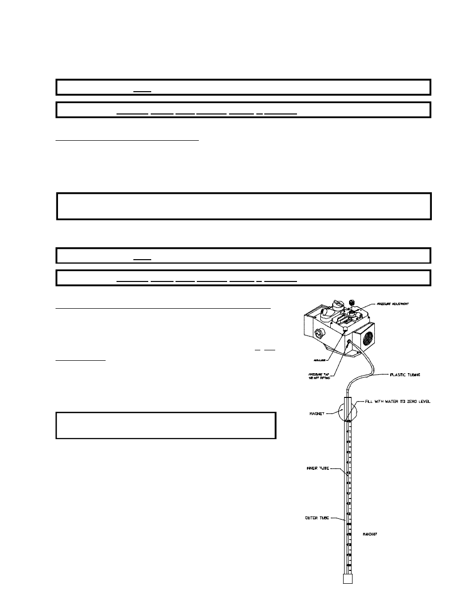
To Test and Adjust Gas (Water Column) Pressure
There are two (2) types of devices commonly used to measure
water column pressure. They are spring/mechanical-type gauges
and manometers. The spring/mechanical-type gauge is not
recommended, because it is easily damaged and not always
accurate. A manometer is simply a glass or transparent plastic
tube with a scale in inches. When filled with water and pressure
applied, the water in the tube rises showing the exact water column
pressure.
NOTE: Manometers are available from the factory by
ordering ADC Part No. 122804.
1. To Test Gas Water Column (W.C.) Pressure:
a. Connect water column test gauge connection to gas valve
pressure tap (1/8” NPT). This pressure tap is located on
the outlet (manifold) side of the valve.
b. Start dryer. With burner on, the correct water column
reading in inches would be:
Natural Gas - 3.5 Inches Water Column (8.7 mb).
L.P. Gas - 10.5 Inches Water Column (26.1 mb).