Iii. installation, Asus p2l-m user’s manual 33 – Asus P2L-M User Manual
Page 33
ASUS P2L-M User’s Manual
33
III. INSTALLATION
Connectors
III. INST
ALLA
TION
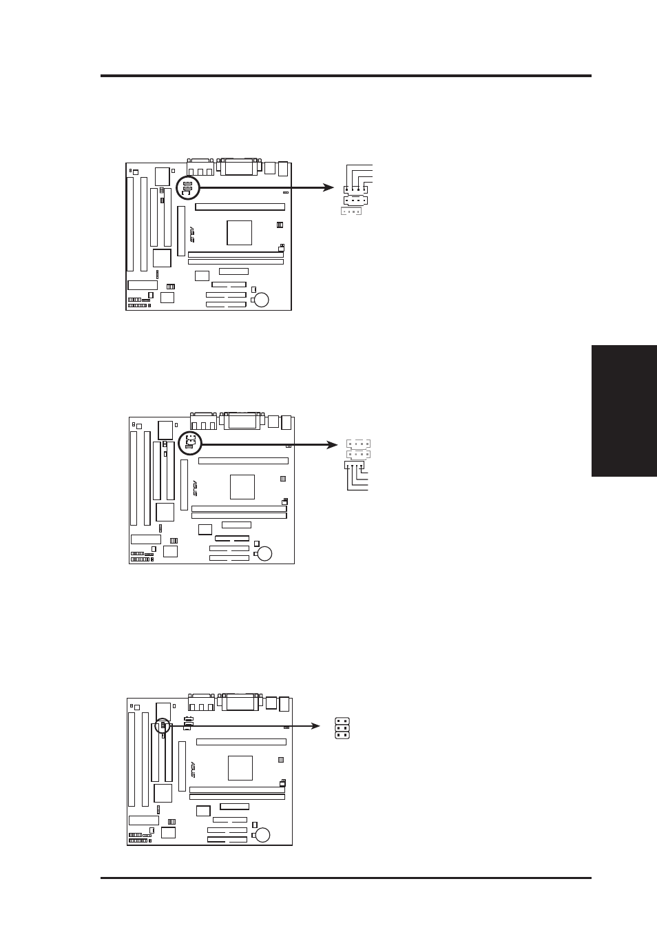
15. Stereo Audio In Connectors (4-pin AUX,CD1)
(with optional onboard audio)
These connectors allow you to receive stereo audio input from such sound sources
as a TV tuner or MPEG card.
R
Right Audio Channel
Left Audio Channel
Ground
Ground
P2L-M Stereo Audio In Connectors
AUX
CD1
NOTE: CD-1 has the same pin
definitions as AUX
16. Stereo Audio In Connector (4-pin CD2) (with optional onboard audio)
This connector allows you to receive stereo audio input from an internal CD-
ROM drive.
R
Left Audio Channel
Right Audio Channel
Ground
Ground
P2L-M Stereo Audio In Connector
17. Digital Audio Interface (6-pin SPDIFO)
This connector is the digital link between the motherboard and your audio de-
vices such as CD player, sampler, or DAT recorder. It allows the digital trans-
mission of audio data in SPDIF (Sony/Philips Digital Interface) Format.
P2L-M Digital Audio Interface
R
TTL: Short this, if output device is TTL level
SPDIFO: Digital Signal OUT
SPDIFI: Digital Signal IN