Installation instructions, Plate position flat bottom cabinet, Cabinet bottom plate position framed recessed – Electrolux EI30BM60MS User Manual
Page 7: Beneath
DETERMINING WALL PLATE LOCATION UNDER YOUR CABINET
C.
Installation Instructions
Plate position
flat bottom
cabinet
Draw a line on the
back wall equal to the
depth of the front
overhang.
to Cooktop
C
3/8" TO EDGE
NOTE: IT IS V
ERY IMPORT
ANT TO
READ AND F
OLLOW THE D
IRECTIONS
IN THE INSTA
LLATION INS
TRUCTIONS
BEFORE PRO
CEEDING W
ITH THIS
REAR WALL T
EMPLATE.
This Rear Wall T
emplate serves
to position the b
ottom
mounting plate a
nd to locate the
horizontal exha
ust
outlet.
1. Use a level to
check that the t
emplate is positio
ned
accurately.
2. Locate and m
ark at least one
stud on the left
or
right side of th
e centerline.
It is
important to us
e at least one w
ood
screw mounted
firmly in a stud t
o support the w
eight
of the microwav
e. Mark two add
itional, evenly s
paced
locations for the
supplied toggle
bolts.
3. Drill holes in t
he marked loca
tions. Where th
ere is
a stud, drill a
3/16" hole for w
ood screws. Fo
r holes
that do not lin
e up with a stud
, drill 5/8" holes
for
toggle bolts.
DO
NOT INSTALL
THE MOUNTIN
G PLATE
AT THIS TIME.
4. Remove the t
emplate from th
e rear wall.
5. Review the In
stallation Instruc
tion book for yo
ur
installation sit
uation.
Locate and m
ark holes to a
lign with holes
in the
mounting plate
.
IMPORTANT:
LOCATE AT L
EAST ONE S
TUD ON EITH
ER SIDE OF
THE CENTER
LINE.
MARK THE L
OCATION FO
R 2 ADDITIO
NAL, EVENLY
SPACED TOG
GLE BOLTS I
N THE MOUN
TING PLATE
AREA.
Locate and m
ark holes to ali
gn with holes
in the
mounting plate
.
IMPORTANT:
LOCATE AT L
EAST ONE S
TUD ON EITH
ER SIDE OF
THE CENTER
LINE.
MARK THE L
OCATION FO
R 2 ADDITIO
NAL, EVENLY
SPACED TOG
GLE BOLTS IN
THE MOUNT
ING PLATE
AREA.
Trim the rear w
all template alo
ng the dotted l
ine.
Trim the rear w
all template alo
ng the dotted l
ine.
12"
4"
Darle vuelta a la
hoja para cons
ultar la
versión en Espa
ñol.
CL
3/8" TO EDGE
NOTE: IT IS VER
Y IMPOR
TANT TO
READ AND F
OLLOW THE
DIRECTIONS
IN THE INST
ALLATION IN
STRUCTIONS
BEFORE PR
OCEEDING W
ITH THIS
REAR WALL T
EMPLATE.
This Rear Wall T
emplate serves
to position the b
ottom
mounting plate a
nd to locate the
horizontal exha
ust
outlet.
1. Use a level to
check that the te
mplate is positi
oned
accurately.
2. Locate and ma
rk at least one s
tud on the left o
r
right side of th
e centerline.
It is
important to us
e at least one w
ood
screw mounted
firmly in a stud
to support the w
eight
of the microwav
e. Mark two add
itional, evenly s
paced
locations for th
e supplied tog
gle bolts.
3. Drill holes in t
he marked loca
tions. Where th
ere is
a stud, drill a
3/16" hole for w
ood screws. Fo
r holes
that do not lin
e up with a stud
, drill 5/8" holes
for
toggle bolts.
DO
NOT INSTALL
THE MOUNTIN
G PLATE
AT THIS TIME
.
4. Remove the te
mplate from the
rear wall.
5. Review the In
stallation Instru
ction book for y
our
installation s
ituation.
Locate and ma
rk holes to alig
n with holes in
the
mounting plate
.
IMPORTAN
T:
LOCATE AT
LEAST
ONE STUD ON
EITHER SID
E OF
THE CENTER
LINE.
MARK THE LOC
ATION FOR 2
ADDITIONAL
, EVENLY
SPACED TOG
GLE BOLTS
IN THE MOUN
TING PLATE
AREA.
Locate and ma
rk holes to alig
n with holes in
the
mounting plate
.
IMPORTANT:
LOCATE AT
LEAST ON
E STUD ON
EITHER SID
E OF
THE CENTER
LINE.
MARK THE LO
CATION FOR
2 ADDITIONAL
, EVENLY
SPACED TOG
GLE BOLTS
IN THE MO
UNTING PLAT
E
AREA.
Trim the rear w
all template along
the dotted lin
e.
Trim the rear w
all template alo
ng the dotted
line.
12"
4"
Darle vuelta a la
hoja para cons
ultar la
versión en Esp
añol.
²
At least 30
″
C
3/8" TO EDGE
NOTE: IT IS V
ERY IMPORTA
NT TO
READ AND FO
LLOW THE DIRE
CTIONS
IN THE INSTAL
LATION INSTRU
CTIONS
BEFORE PROC
EEDING WITH
THIS
REAR WALL
TEMPLATE.
This Rear Wall T
emplate serves to
position the botto
m
mounting plate a
nd to locate the h
orizontal exhaust
outlet.
1. Use a level to c
heck that the tem
plate is positione
d
accurately.
2. Locate and ma
rk at least one st
ud on the left or
right side of th
e centerline.
It is imp
ortant to use at le
ast one wood
screw mounted fi
rmly in a stud to s
upport the weigh
t
of the microwave
. Mark two additi
onal, evenly spa
ced
locations for the s
upplied toggle bo
lts.
3. Drill holes in th
e marked locatio
ns. Where there is
a stud, drill a 3
/16" hole for woo
d screws. For ho
les
that do not lin
e up with a stu
d, drill 5/8" holes
for
toggle bolts.
DO
NOT INSTALL T
HE MOUNTING
PLATE
AT THIS TIME.
4. Remove the te
mplate from the r
ear wall.
5. Review the Ins
tallation Instructio
n book for your
installation situ
ation.
Locate and m
ark holes to align
with holes in th
e
mounting plate
.
IMPORTANT:
LOCATE AT LE
AST ONE STU
D ON EITHER
SIDE OF
THE CENTER
LINE.
MARK THE LO
CATION FOR
2 ADDITIONA
L, EVENLY
SPACED TOG
GLE BOLTS IN
THE MOUNTIN
G PLATE
AREA.
Locate and ma
rk holes to align
with holes in th
e
mounting plate
.
IMPORTANT:
LOCATE AT
LEAST ONE S
TUD ON EITH
ER SIDE OF
THE CENTER
LINE.
MARK THE LO
CATION FOR 2
ADDITIONAL,
EVENLY
SPACED TOGG
LE BOLTS IN
THE MOUNTIN
G PLATE
AREA.
Trim the rear w
all template alo
ng the dotted lin
e.
Trim the rear wa
ll template alon
g the dotted lin
e.
12"
4"
Darle vuelta a la h
oja para consultar
la
versión en Españ
ol.
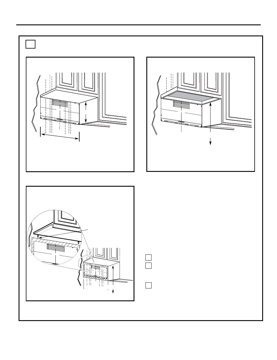
Your cabinets may have decorative trim that
interferes with the microwave installation. Remove
the decorative trim to install the microwave properly
and to make it level.
THE MICROWAVE MUST BE LEVEL.
Use a level to make sure the cabinet bottom is level.
If the cabinets have a front overhang only, with no
back or side frame, install the mounting plate down
the same distance as the front overhang depth. This
will keep the microwave level.
Measure the inside depth of the front overhang.
Draw a horizontal line on the back wall an equal
distance below the cabinet bottom as the inside
depth of the front overhang.
For this type of installation with front overhang
only, align the mounting tabs with this horizontal
line, not touching the cabinet bottom as described
in Step D.
Draw a vertical line on
the wall at the center of
the 30
″
wide space.
Tape the Rear Wall
Template onto the wall
matching the centerline
and touching the
bottom of the cabinet.
to Cooktop
Draw a vertical line on the wall at the center of the
30
″
space.
Tape the Rear Wall Template onto the wall
matching the centerline and touching the bottom
C
3/8" TO EDGE
NOTE: IT IS V
ERY IMPORTA
NT TO
READ AND FO
LLOW THE DI
RECTIONS
IN THE INSTAL
LATION INSTR
UCTIONS
BEFORE PRO
CEEDING WIT
H THIS
REAR WALL T
EMPLATE.
This Rear Wall T
emplate serves to
position the botto
m
mounting plate a
nd to locate the h
orizontal exhaus
t
outlet.
1. Use a level to c
heck that the tem
plate is positione
d
accurately.
2. Locate and m
ark at least one s
tud on the left or
right side of th
e centerline.
It is
important to use
at least one woo
d
screw mounted fi
rmly in a stud to su
pport the weight
of the microwave
. Mark two additio
nal, evenly space
d
locations for the s
upplied toggle bo
lts.
3. Drill holes in th
e marked locatio
ns. Where there i
s
a stud, drill a 3
/16" hole for woo
d screws. For ho
les
that do not line
up with a stud, d
rill 5/8" holes for
toggle bolts.
DO
NOT INSTALL T
HE MOUNTING
PLATE
AT THIS TIME.
4. Remove the te
mplate from the r
ear wall.
5. Review the Insta
llation Instruction
book for your
installation si
tuation.
Locate and ma
rk holes to align
with holes in th
e
mounting plate.
IMPORTANT:
LOCATE AT L
EAST ONE
STUD ON EIT
HER SIDE OF
THE CENTER
LINE.
MARK THE LOC
ATION FOR 2 A
DDITIONAL, E
VENLY
SPACED TOG
GLE BOLTS IN
THE MOUNTIN
G PLATE
AREA.
Locate and ma
rk holes to align
with holes in th
e
mounting plate
.
IMPORTANT:
LOCATE AT LE
AST ONE STUD
ON EITHER S
IDE OF
THE CENTER
LINE.
MARK THE LO
CATION FOR 2
ADDITIONA
L, EVENLY
SPACED TOG
GLE BOLTS IN
THE MOUN
TING PLATE
AREA.
Trim the rear w
all template alo
ng the dotted lin
e.
Trim the rear w
all template alo
ng the dotted lin
e.
12"
4"
Darle vuelta a la
hoja para consu
ltar la
versión en Españ
ol.
cabinet bottom
Plate position
framed
recessed
1
3
2
300″0
30
cabinet frame.
300″0
30
17-1/
″
2
-beneath
-beneath
with front overhang
Plate position
bottom
-beneath recessed
cabinet
EN-7
- 30 Inch Over-the-Range Convection Microwave Oven Installation Guide 30 Inch Over-The-Range Microwave Installation Instructions 24 Inch Over the Range Microwave Installation Guide 30 Inch Over the Range Microwave Installation Guide Gallery Series 30 Inch Over the Range 1000W Microwave Installation Guide