UEi Test Instruments DM384 User Manual
Page 9
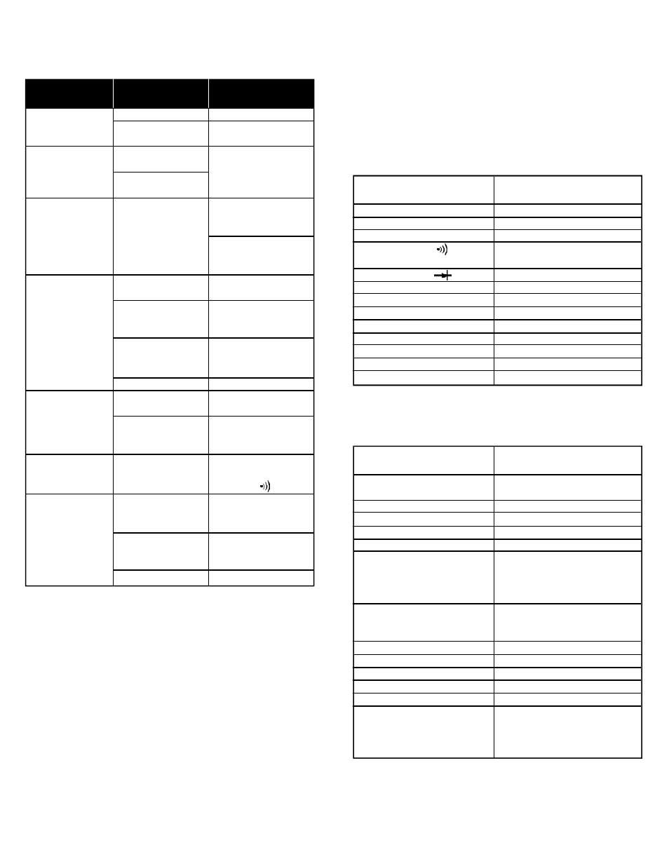
Tro u b l e s h o o t i n g
This unit contains no user serviceable parts beyond those listed in the
table. In the event your instrument is physically damaged or does not
function properly after taking the listed action, please return the
instrument to UEi following the warranty and service instructions.
S p e c i f i c a t i o n s
Measurement limits
Note: When servicing the meter, use only the replaceable
parts specified.
Physical Specifications
DM384-MAN
P. 8
If I See This
Malfunction
Instrument does not
turn on
Instrument turns on
but LCD indicates
some unreasonable or
unchanging value
A value appears on
screen with no input
applied
A known value is not
displayed on the LCD
when measured
Meter reading
is unstable
No audible tone
with near zero
resistance value
Amps readings do
not work
I Should
Check For
Battery voltage
On/Off switch
position
MAX button pressed
HOLD button pressed
Stray voltage
MAX and HOLD
buttons pressed
Bad test lead connections
Defective test leads
Battery voltage
Offset rotary
selector knob
Bad test lead contacts
Improper selector position
Proper switch position
Proper test lead
port position
Blown fuse
Then Take This
Corrective Action
Replace low battery
Ensure button moves freely
and is in the on position
Look for MAX HOLD icons
displayed on the LCD
-Turn off one or
both buttons
Short test leads together -
If a value near 000 appears,
instrument is OK
Move meter and leads away
from devices that create
electrical fields
Turn off one or both buttons
(check for icons on LCD)
Ensure test leads are fully
inserted and free of
corrosion or dirt
Short test leads together in
the 400 ohm scale - Expect
less than .5Ω
Replace low battery
Ensure knob is firmly placed
in switch position
Ensure there is no insulating
material, dirt or debris at
contact points
Tone sounds only in
continuity mode. Place
selector in position
Ensure switch is in proper
AC or DC amps position
(ACA or DCA)
Ensure the red test lead is
plugged into the appropriate
amps port
Replace blown fuse
Frequency (Hz)
ACV (at 50 to 500 hertz)
DCV
DC mV
Continuity ( )
Diode Test ( )
Resistance (Ohms/Ω)
Capacitance
DC µA
DC mA
DC 10A
AC µA
AC mA
AC 10A
1 Hertz minimum to
400 Megahertz maximum
750 V CAT II (600 V CAT III)
1000 V CAT II (600 V CAT III)
400 Millivolts
400Ω - Tone sounds at
approximately 30Ω or less
3 V DC (voltage drop)
40MΩ
40,000 Microfarads
Center left port - 400 Micro amps
Center left port - 400 Micro amps
Far left port - 10 Amps
Center left port - 400 Micro amps
Center left port - 400 Milliamps
Far left port - 10 Amps
Maximum voltage
on ground terminal
Numerical digital display
Analog bar-graph
Storage temperature
Operating temperature
Altitude
Relative humidity
Temperature coefficient
Battery type
Battery life (typical)
Size (H x W x L, in.)
Weight (approximate)
Drop test
Safety standards
600 V - CAT III
1000 V - CAT II
0.8”, 3-3/4 digit
4000 count - updates 4 times per second
42 segment - updates 20 times per second
-4˚ to 140˚F (-20˚ to 60˚C)
32˚ to 113˚F (0˚ to 45˚C)
6 560’ (2000 M)
0% to 80% at 32˚ to 95˚F
(0˚ to 35 ˚ C )
0% to 70% at 95˚ to 113 ˚ F
( 35˚ to 45˚C)
0 .1 x (specified accura cy ) / ˚ C
when ambient temperature is
<64˚F or > 82˚F (<18˚C or > 28 ˚ C )
9V, NEDA, 1604 or 6LR 61
80 hours (alkaline)
7- 3 /4” x 3-7/8” x 2”
21.1 oz. (600 g)
10 ’
IE C 1010 - 1
(600 Volts overvoltage ca t e g o ry III )
( 1000 Volts overvoltage ca t e g o ry II )
and the EMC directive