UEi Test Instruments DM384 User Manual
Page 8
Battery Replacement
Always use a fresh replacement battery of the specified size and type.
Immediately remove the old or weak battery from the meter and
dispose of it in accordance with your local disposal regulations. Batteries
can leak chemicals that corrode electronic circuits. If your meter is not
going to be used for a month or more, remove and store the battery in
a place that will not allow leakage to damage other materials.
WARNING!
Disconnect the test leads from the circuit under test and from the meter
prior to removing or installing batteries.
To install a new battery, follow these procedures:
1. Turn off the meter.
2. Remove the rubber boot from the meter, starting at the top.
3. Place meter face down on a clean cloth.
4. Remove the screws from the rear case. Two machined screws
fasten the bottom and two self-tapping screws fasten the top.
5. Separate the two halves to expose the battery.
6. Remove and discard the old battery. Always dispose of old batteries
promptly in a manner with local disposal regulations.
WARNING!
Under no circumstances should you expose batteries to extreme heat or
fire as they may expose and cause injury.
7. Place a fresh 9V battery in the battery clip.
8. Reassemble the meter.
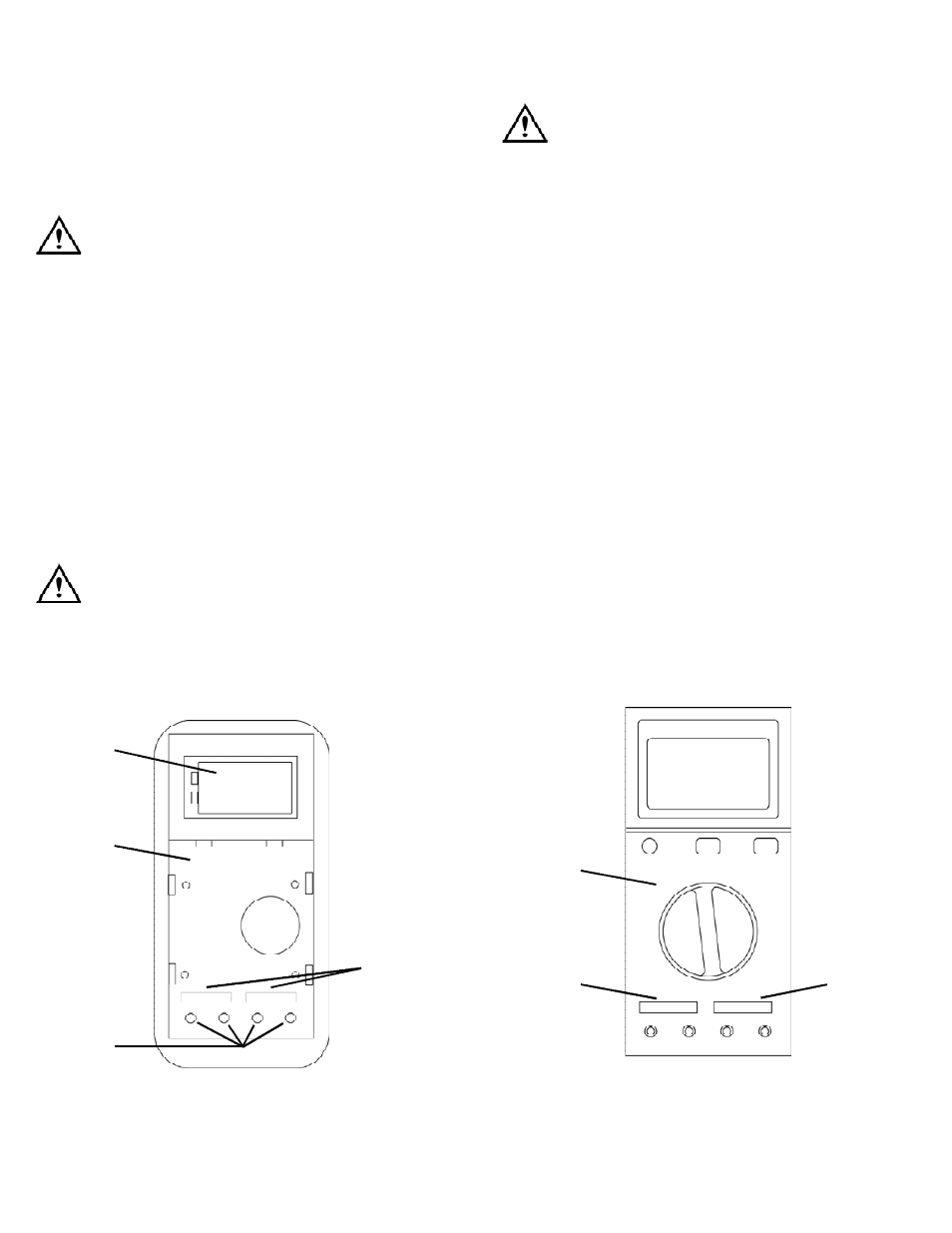
View of meter face down with back cover off.
1. B a t t e ry
2. P CB
3. Test lead ports
4. Fuses, under PCB
Fuse Replacement
WARNING!
Disconnect the test leads from the circuit under test and from the meter
prior to removing or installing fuses! Replace the bottom fuse with the
fuse specified for this meter ONLY!
To replace a blown fuse, perform the following procedures:
1. Turn off the meter.
2. Remove the rubber boot from the meter, starting at the top.
3. Place meter face down on a clean cloth.
4. Remove the screws from the rear case. Two machined screws
fasten the bottom and two self-tapping screws fasten the top.
5. Separate the two halves.
6. Lift the entire printed circuit board (PCB) housing up and away from
the front half of the meter. Lift the PCB housing straight up as there
are metal cylinders inside the test lead insulators that must slide
out with it.
7. Turn the housing over to expose the fuses.
8. Check to ensure the fuse is bad by confirming that there is no
c o n t i n u i ty between the metal ca p s .
Note: If the fuse is good, check for corrosion at the fuse clips and
ensure clips are tight around the fuse.
9. Insert a new fuse, or reinsert the good one.
10. Reassemble the meter.
View of PCB housing face-up with cover off.
1. P CB
2. 12A, 250V Fu s e
3. 0.5A, 660V Fu s e
DM384-MAN
P. 7
1
2
3
1
2
4
2