UEi Test Instruments C75OILKIT User Manual
Page 9
C75-MAN
P. 7
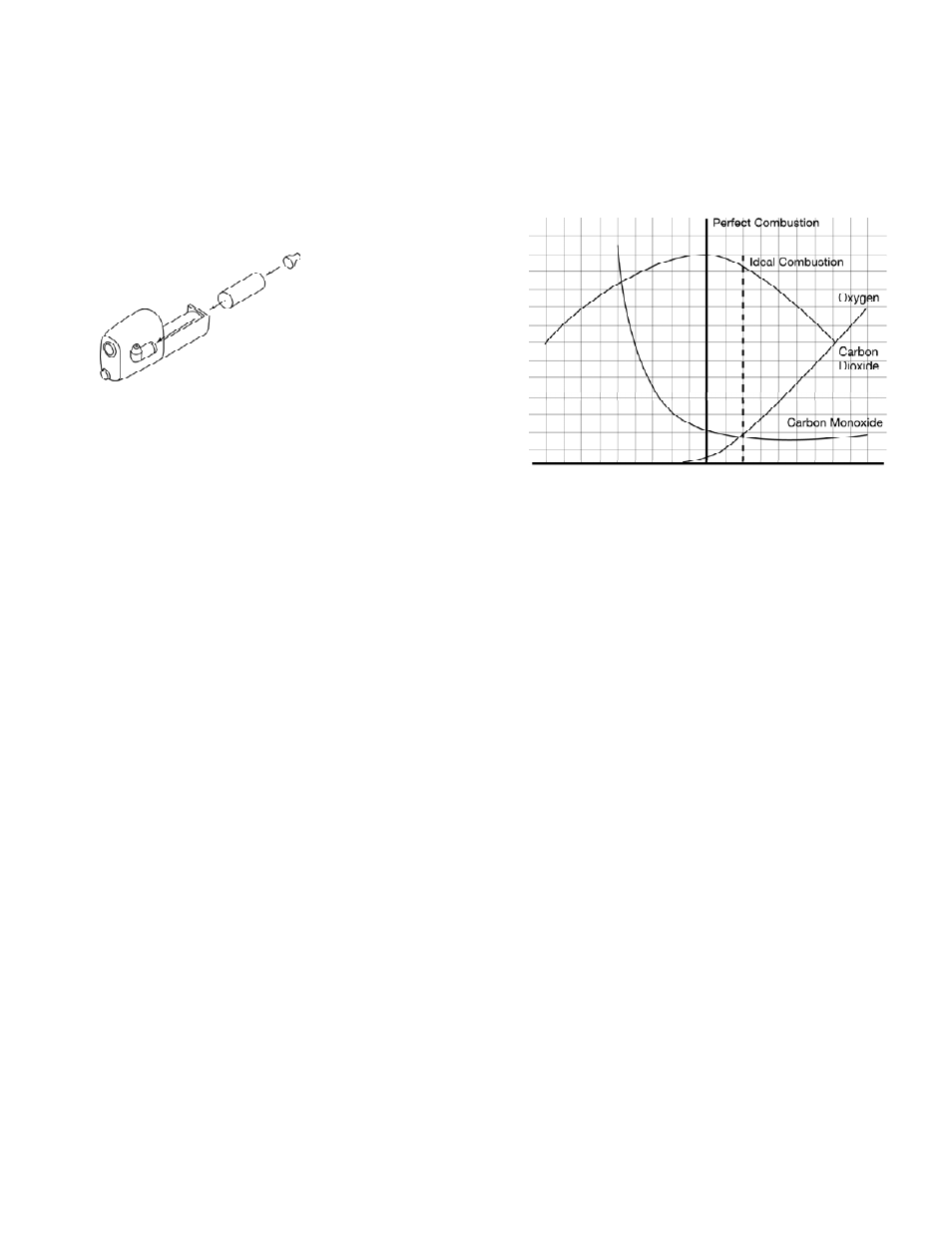
Below is a graph of typical combustion, showing the point of perfect
combustion and an approximate location for ideal combustion. You will
notice that by moving farther to the right on the air rich side (high
amounts of excess air), the pollutants (CO) don’t drop any further. This
is where you only lower efficiency. On the left side (fuel rich or starved
for air) you see a dramatic increase in carbon monoxide (CO), indicat-
ing that a portion of the fuel is not being converted to heat.
Combustion Efficiency Calculation
The efficiency calculation is based upon British Standards BS845.
This identifies three sources of loss associated with fuel burning:
Losses due to flue gasses:
Dry Flue gas loss, moisture and
hydrogen, sensible heat of water
vapor, unburned gas
Losses due to refuse:
Combustible in ash, riddlings
and dust
Other losses:
Radiation, convection, conduction
other unmeasured losses
Since the fuel air mixture is never consistent there is the possibility of
unburned/partially unburned fuel passing through the flue. This is rep-
resented by the unburned carbon loss.
Losses due to combustible matter in ashes, riddlings, dust and grit,
radiation, convection and conduction are not included.
If condensate spills onto the skin or clothing, clean off immediately
using fresh water, seek medical advice if problems occur. Ensure plug is
replaced before performing combustion tests.
Changing the Particle Filter
This is a very important part of the analyzer and should be changed reg-
ularly. It prevents dust and dirt particles from entering the pump and
sensors that will cause damage. The filter MUST be changed when it
appears discolored.
Remove water-trap assembly from the analyzer as shown above.
Remove the filter and plastic holder from the housing. Discard the filter
element but keep the holder to fit to the new filter. Clean the inside of
the filter housing with a suitable soft cloth. Fit the holder onto the new
filter element and then insert into the housing. Refit the housing onto
the analyzer.
C o m b u s t i o n
Combustion Theory
In its simplest form, combustion is the combining of oxygen (O
2
) from
the air with hydrogen (H) and carbon (C) from the fuel to form carbon
dioxide (CO
2
), water (H
2
O) and energy (light and heat).
Perfect combustion occurs when all of the carbon and hydrogen in the
fuel unite with all of the oxygen supplied by the air. This is also referred
to as “STOICHIOMETRIC Combustion”.
In the real world perfect combustion is nearly impossible to achieve.
When tuning a combustion appliance, the goal is to come close to this
target to minimize losses and excess emissions. One method is to adjust
the amount of air supplied to the combustion area. Too little combus-
tion air, and there will not be enough oxygen to unite with the hydrogen
and carbon. This will result in partially burnt fuel, and the creation of
carbon monoxide (CO), smoke, and lower efficiency. Too much air will
also lower efficiency because the high amount of excess air draws heat
away from the combustion area up the flue (increase in ∆T, difference
between flue temperature and ambient or inlet). If the amount of excess
air is too high, it will also move past the heat exchanger too quickly,
resulting in a lower amount of heat transferring to the target.
Insert a new filter
Rich
Lean