Table of identifiers (codes) – TOHO ELECTRONICS TTM-10L User Manual
Page 17
17
7. Table of identifiers (codes)
¢ For the setting range, selection items, initial values, etc., see "Operation Manual- Standard
Version" separately attached.
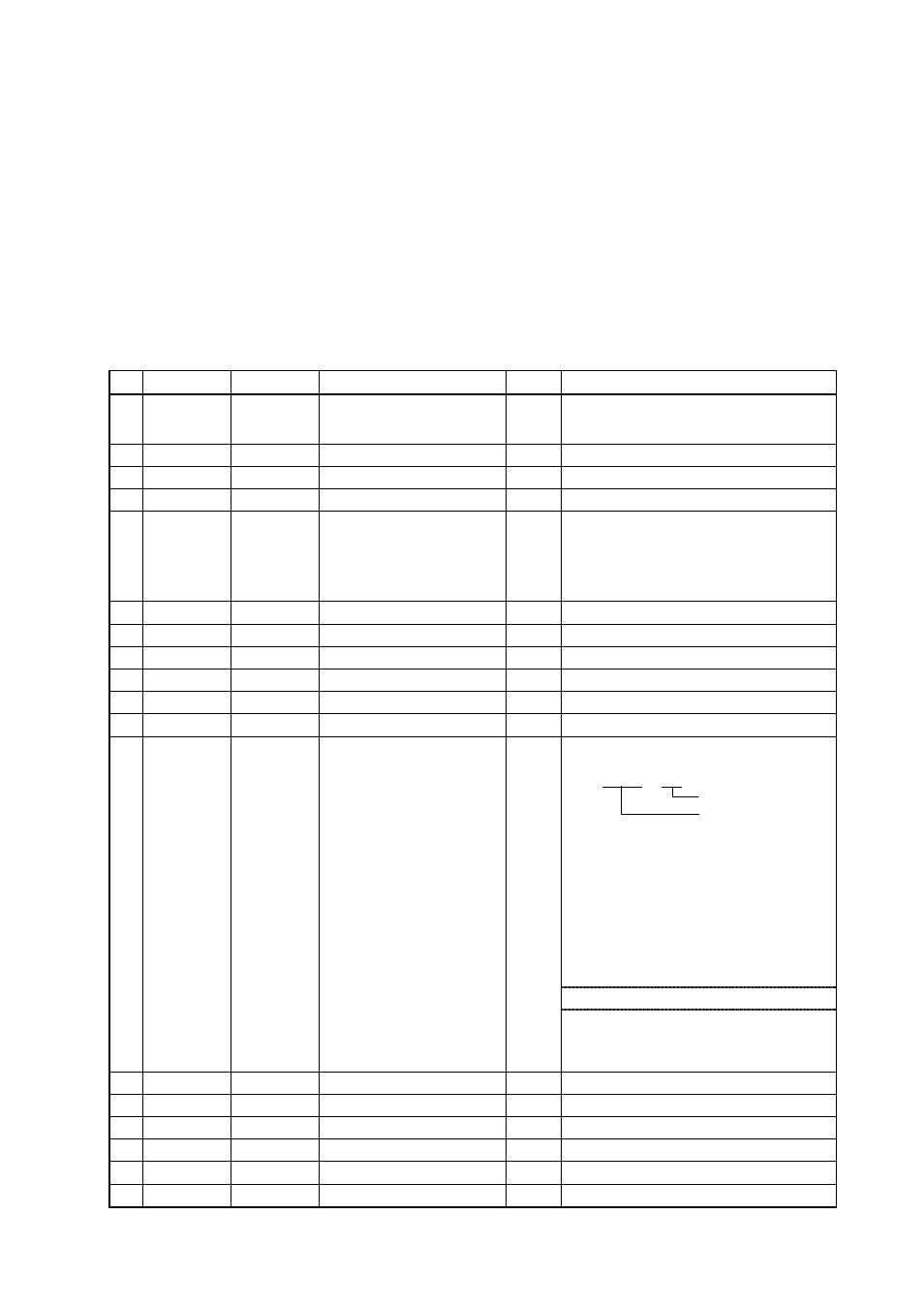
a)
Character number or symbol in the operation flow described in "Operation
Manual - Standard Version" (separate volume)
é b) Identifier:
This code represents an item. Enter this code in the identifier field in the
message. The □ in the frame represents an SP (ASCII code: 20H).
c) Character:
The character to be displayed on the screen of this product.
d) Name:
Item name
e) R/W:
This specifies which is possible: reading, writing, or both.
f) Description:
a)
Identifier
Character
Name
R/W
Description
A
PV1
Setting value (PV)
R
Use it as monitor for measurements (PV).
When overscale: HHHHH
When underscale: LLLLL
B
□SV
Control setting value (SV)
R/W
Target value of control *1
C
1L1
EV lower limit setting
R/W
R/W the EV lower setting *3, *4
D
1H1
EV upper limit setting
R/W
R/W the EV upper setting *3, *5
E
□AT
AT start/release
R/W
R/W the auto-tuning status *1, *2
At start: 00001
At release: 00000
When "00001" is received, the auto-tuning
starts; when the auto-tuning stops, the
indication becomes "00000."
1
□P1
Proportional band
R/W
R/W the proportional band *1
2
□I1
Integral time
R/W
R/W the integral time *1, *2
3
□D1
Derivative time
R/W
R/W the derivative time *1, *2
4
□T1
Proportional cycle
R/W
R/W the proportional cycle *1, *2
5
□C1
Control sensitivity
R/W
R/W the control sensitivity *1, *6
6
□IO
Input/output type
R/W
R/W the input/output type *10
0 0 0 0 0
Output type
Input type
Input type
00: K thermocouple
01: J thermocouple
02: E thermocouple
03: T thermocouple
04: R thermocouple
05: S thermocouple
06: N thermocouple
07: W5Re/W26Re
10: Pt100
11: JPt100
20: Current (4-20 mA)
Output type
0: None
1: Relay contact output
2: SSR drive output
7
SLL
SV limiter lower limit
R/W
R/W the SV limiter lower limit
8
SLH
SV limiter upper limit
R/W
R/W the SV limiter upper limit
9
CNT
Control type
R/W
R/W the control type *1
10
PVS
PV compensation
R/W
R/W the PV compensation
11
PBB
Manual reset
R/W
R/W the manual reset *1, *2
12
□CP
Off point position
R/W
R/W the off point position *1, *6