Timeguard FFM250 User Manual
Page 3
3. Preparation of Surface
4. Planning Mat/Cable Layout
Wood Floor
This will generally be either floorboards or chipboard panels. With floorboards
any loose boards will need to be firmly fixed and it will be necessary to cover
the complete floor with 20mm plywood sheeting fixed at 200mm centres.
With chipboard panels ensure they are all firmly fixed and cover with plywood
as above. The use of a primer recommended by your screed/adhesive supplier
is essential. This must be applied to the complete floor surface to be tiled.
Grooves will need to be made to accommodate the cable/mat flying lead
(cold cable) and the temperature probe with its flying lead as these are
thicker than the heating cables (mat or cable).
Concrete/Screed Floor
Repair any fissures or patches with a cement sand mixture with PVA added to
improve adhesion. The use of a primer recommended by your screed/adhesive
supplier is essential. This must be applied to the complete floor surface to
be tiled.
Grooves will need to be made to accommodate the cable/mat flying lead (cold
cable) and the temperature probe with its flying lead as these are thicker than
the heating cables (mat or cable).
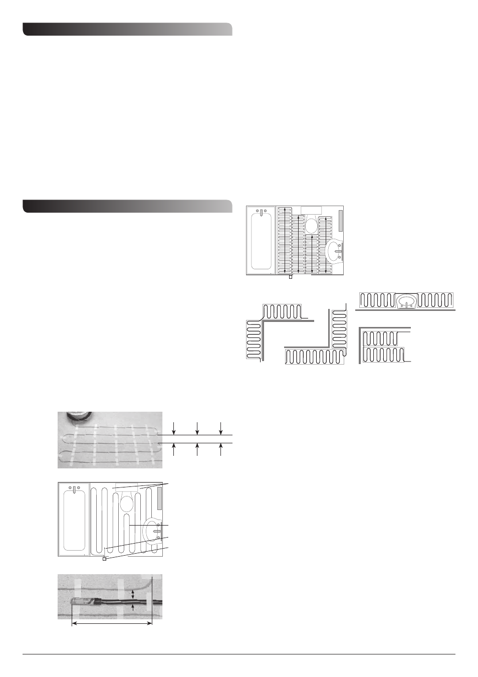
Figure 2
Figure 4
Figure 3
Cable Layout
The layout and installation of mat/cable must be carried out in accordance
with these instructions. If there is any doubt about how to proceed please
contact the Helpline on 020 8450 0515 or a competent professional person.
For wood floors the gap between the cable runs should be 82mm (see figure 1).
This gives 120W/m
2
. For concrete/screed floors the gap between cable runs
should be 62mm, this gives 160W/m
2
. To give 200W/m
2
the gap between cable
runs should be 50mm.
Initially decide on a location for the RCD and controller* then plan the run of
the cold cable to the start of the heating cable and the run of the temperature
probe flying lead, remembering that no cable should cross over or under any
other or the temperature probe which should be positioned as in figure 3.
The cold cable and probe flying lead are 4m long and may be shortened
if necessary.
Cables should be run backwards and forwards between walls or obstructions
(see the example given in figure 2). Cables should not be run under
permanent fixtures. The cables should not get closer to the tiling edge than
50mm and should clear permanent fixtures by the same amount.
If the largest cable in the range is not long enough a second cable can be used
with the two cold cables connected to the controller – black to black to
controller live output and blue to blue to controller neutral output.
* These should not be located in a bathroom or near a sink or cooking facilities in a kitchen.
Mat Layout
These have a fixed output of 160W/m
2
and are suitable for concrete/
screed floors.
Initially decide on a location for the RCD and controller* then plan the run of
the cold cable to the start of the heating mat and the run of the temperature
probe flying lead remembering that no cable should run under or over any
other or the temperature probe which should be positioned as in figure 3.
The cold cable and probe flying lead (both 4m in length) may be shortened
as necessary.
Mats should run backwards and forwards between walls or obstructions. The
techniques shown in figures 4 and 5 may prove useful. When cutting the mat
webbing to give direction changes or bypassing of obstacles take care not to
cut or damage the heating cable. Mat runs should be separated by at least
30mm and should not be run under permanent fixtures. The cables within the
mats should not get closer to the tiling edge than 50mm and should clear
permanent fixtures by the same amount. If the longest mat in the range is not
long enough to cover the required area a second mat or cable can be used
with the two cold cables connected to the controller controller – black to black
to controller live output and blue to blue to controller neutral output.
* These should not be located in a bathroom or near a sink or cooking facilities in a kitchen.
A groove should be made
in the floor surface to
bring the upper surface of
the temperature probe and
cable level with the
heating cable.
Conserve energy by
avoiding areas (such as
under water cistern) which
are not a normal area for
foot contact.
Heating Cable
Temperature Probe
Controller (must not be
mounted inside bathroom
150mm
=
Flexi-Fast Mat Layout
These give an output of between 133 and 200W/m
2
depending on the degree
of stretch (maximum stretch gives 133W/m
2
).
Initially decide on a location for the RCD and controller* then plan the run of
the cold cable to the start of the heating mat and the run of the temperature
probe flying lead remembering that no cable should run under or over any
other or the temperature probe which should be positioned as in figure 3.
The cold cable and probe flying lead (both 4m in length) may be shortened
as necessary.
Mats should run backwards and forwards between walls or obstructions.
Generally it will be sufficient to pin the mat at the start and finish of each
run if there is a degree of stretch in the mat. The techniques shown in figures
4 and 5 may prove useful. When cutting the mat webbing to give direction
changes or bypassing of obstacles take care not to cut or damage the heating
cable. Mat runs should be separated by at least 30mm and should not be run
under permanent fixtures. The cables within the mats should not get closer to
the tiling edge than 50mm and should clear permanent fixtures by the same
amount. If the longest flexi-fast mat in the range is not long enough to cover
the required area at the required W/m
2
a second flexi-fast mat or cable can be
used with the two cold cables connected to the controller – black to black to
controller live output and blue to blue to controller neutral output.
* These should not be located in a bathroom or near a sink or cooking facilities in a kitchen.
Obstacle cut
Corner cuts
Plain wall cut
Empty square
Filled square
Figure 5
When cutting the mat
webbing to give direction
changes or the bypassing
of obstacles take care not
to cut or damage the
heating cable.
=
Figure 1
82mm
Wood
floors
200W/m
2
160W/m
2
120W/m
2
62mm
50mm
Concrete/
screed floors