Parts included, Tools and parts needed, Selecting a location – Timeguard PDWM1500 User Manual
Page 3: Connection, Installation, Introduction
2
Introduction
The PDWM1500.1 utilises passive infrared technology to
detect heat radiation of moving human bodies.Upon
detection, the
lighting load will illuminate for
a user-determined time period. An integral daylight
sensor ensures all day or night-only operation.
Important Information: Light Pollution and
Considerate Lighting
Please be aware of the annoyance over-lighting an area
can cause to your immediate neighbours. Light
pollution caused by incorrectly installing a unit or
over-lighting an area can be limited by carefully
considering the location and position of your unit
before installation. The light spread on all halogen
floodlights can be reduced by angling the floodlight
downwards on the mounting bracket. This will also
concentrate the light on your property and limit the
potential inconvenience of the light shining into your
neighbours windows etc.
Please see Selecting a Location for information on
choosing the optimum location for any security light
controlled by this unit.
Parts included
• PIR Sensor unit.
• Instruction manual. Please keep safe for future
reference.
• Accessory Pack. Includes 2x screws.
Tools and parts needed
• Terminal or Electricians screwdriver.
• Small philips screwdriver.
• Wire
• Suitable mains interconnect cable.
This product is suitable for indoor use only. Connected
load must not exceed maximum 2300W Halogen
or 400W fluorescent/low energy lighting.
Do not
to install if you are suffering from
nausea or dizzy spells or on medication with similar
side effects. If in any doubt, consult a qualified
electrician.
Not suitable for use with discharge lighting.
Selecting a location
The motion detector has a number of detection zones,
at various vertical and horizontal angles as shown (see
diagram A).
A moving human body needs to cross/enter one of
these zones to activate the sensor. The best all-round
coverage is achieved with the unit wall mounted at the
optimum height of 1m.
up
Walk Test Procedure
TIME - Fully anti-clockwise (Test Mode)
DUSK - Fully clockwise
The unit will now operate during daytime as well as at
night, illuminating the lamp for approx. 5 seconds each
time. This allows testing to be carried out to establish
whether the sensor is covering the required area.
The lamp will immediately illuminate as the unit goes
through its "warm-up" period. A
approximately 1
minute the lamp will extinguish. Try to remain outside
the detection area during the warm-up period.
Walk around the sensor to establish the detection area.
The sensor will detect within an approximately 9 metre
diameter circle from the centre of the sensor location with a
3m ceiling.
As you cross a detection "zone" the lamp will illuminate.
Now stand still until the lamp extinguishes (this should
take approx. 5 seconds).
Start moving
As you cross each
"zone" the lamp will illuminate.
Repeat the above, walking at various distances and
angles to the unit. This will help you to confirm the
detection
.
Time On
Lux
Dusk/Dawn
Careful positioning of the sensor will be required to
ensure optimum performance. See diagram A detailing
detection range and direction.
The sensor is more sensitive to movement ACROSS its
field of vision than to movement directly TOWARDS
(see diagram B). Therefore position the unit so that the
sensor looks ACROSS the likely approach path.
Avoid positioning the sensor where there are any
sources of heat in the detection area (extractor fans,
tumble dryer exhausts etc.) including opposite any
other light sources such as other security lights.
Reflective surfaces (ie pools of water or white-painted
walls) and overhanging branches may cause false
activation under extreme conditions.
During extreme weather conditions the motion sensor
may exhibit unusual behaviour. This does not indicate
a fault with the sensor. Once normal weather conditions
return, the sensor will resume normal operation.
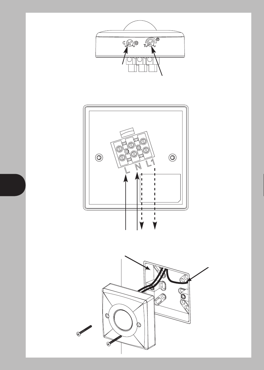
Connection
Switch off the main power suppy or wall switch.
Connect the mains supply cable Live core (brown) to L
and Neutral core(Blue) to N terminal.
Connect the lighting cable Neutral core (blue) to the
same N terminal and Lighting Live core (brown) to
the L1 terminal on the unit (see diagram D):-
NEUTRA L (Blue)
N
LIVE (Brown)
L1
LIVE (Brown)
L
Connect the Earth wire (Green/yellow) to the Earth
terminal on wall box.
When wiring is complete, set the two adjustment
controls on the side of the unit (diagram C) to the
following positions:
TIME -Fully anti-clockwise (Test Mode).
DUS K - Fully clockwise.
Fit the sensor unit to ceiling wall box and secure it
with two fixing screws provided.(Diagram E)
Installation
IMPO RTANT
Switch off the electricity at the fuse box by removing the
relevant fuse or switching off
the circuit breaker before proceeding with the installation.
All
should be installed by competent person in
accordance with IEE Wiring Regulations (BS7671)
choosing a suitable location (see previous section)
install the unit as follows:
The unit is suitable for connection to a 230 V ac 50Hz
electricity supply. It is suggested that 3-core round
flexible cable of 1.5 sq. mm gauge is used. An isolating
switch should be installed to switch the power to the unit
ON & OFF. This allows the sensor to be easily switched
off when not required or for maintenance purposes
C
A
B
D
E
L
N
L1
Switched
Load
OUT
Mains
Supply
IN
Wall box
Connect Earth wire
to wall box Earth terminal
1m
5 ~10m Secondary zone
0~5m Primary zone
More
sensitive
Less
sensitive
5
2
3
4
6
D
E
Wall box
Connect Earth wire to
wall box Earth terminal
The Lux and Time controls should be
at the bottom when installed.
Lux
Dusk/Dawn
setting
Mains
Supply
IN
Switched
Load
OUT
L
N
L1
Time On
setting
C