Takagi T-M50 User Manual
Page 25
- 25 -
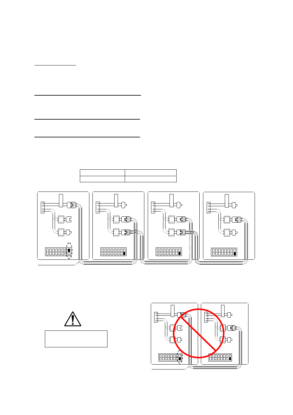
The dark squares indicate the direction
the dipswitches should be set to.
Easy-Link Connection Procedures
1. Choose one of your units as the “PARENT” unit.
2. “The PARENT”
Locate the lower bank of dipswitches to the right of the 7-seg. LED on the central
computer board of the unit that you select to be the “PARENT” unit. Change dipswitch No.
8 to “ON”. Do not change any of the dipswitches on the “CHILD” units.
3. Between the “PARENT” and the “CHILD-1”
Connect the “PARENT connector” of the “PARENT unit” to the “[1] connector” of the
“CHILD-1” unit.
4. Between the “CHILD-1” and the “CHILD-2”
Connect the “[2] connector” of the “CHILD-1” unit to the “[1] connector” of the “CHILD-2” unit.
5. Between the “CHILD-2” and the “CHILD-3”
Connect the “[2] connector” of the “CHILD-2” unit to the “[1] connector” of the “CHILD-3” unit.
6. Make sure the 7-seg. LED of all the unit’s computer boards display the unit #. The numbering
system automatically allocates the unit # to each water heater in the Easy-Link system, in
accordance with the table below.
CAUTION
Unless you change dipswitch No. 8 of the “PARENT” unit to “ON”, the system will not
work as an Easy-Link system. The units will work as individual units.
PARENT unit
Unit # : 1
CHILD units
Unit# : 2, 3 and 4
Wrong dipswitch setting
on the “PARENT
”
unit
Communication cable
Connectors
P
A
R
E
N
T
Connectors
P
A
R
E
N
T
Connectors
P
A
R
E
N
T
Connectors
P
A
R
E
N
T
Lower bank of Dipswitch
OFF
ON
Lower bank of Dipswitch
OFF
ON
Lower bank of Dipswitch
OFF
ON
1 2 3 4 5 6 7 8
1 2 3 4 5 6 7 8
1 2 3 4 5 6 7 8
11
22
11
22
11
22
11
22
Lower bank of Dipswitch
OFF
ON
1 2 3 4 5 6 7 8
PARENT unit
CHILD-1 unit
CHILD-2 unit
CHILD-3 unit
Communication cable
P
A
R
E
N
T
P
A
R
E
N
T
1
Lower bank of Dipswitch
2 3 4 5 6 7 8
OFF
ON
Connectors
Connectors
11
22
1
Lower bank of Dipswitch
2 3 4 5 6 7 8
OFF
ON
11
22
PARENT unit
CHILD-1 unit