Mounting of, On to the duct, Mounting instruction – ROTRONIC CF3-D User Manual
Page 3: Cf3-d
Dokument
IMA 204
Rev
2
Page
3 (7)
Mounting of
CF3-D
on to the duct.
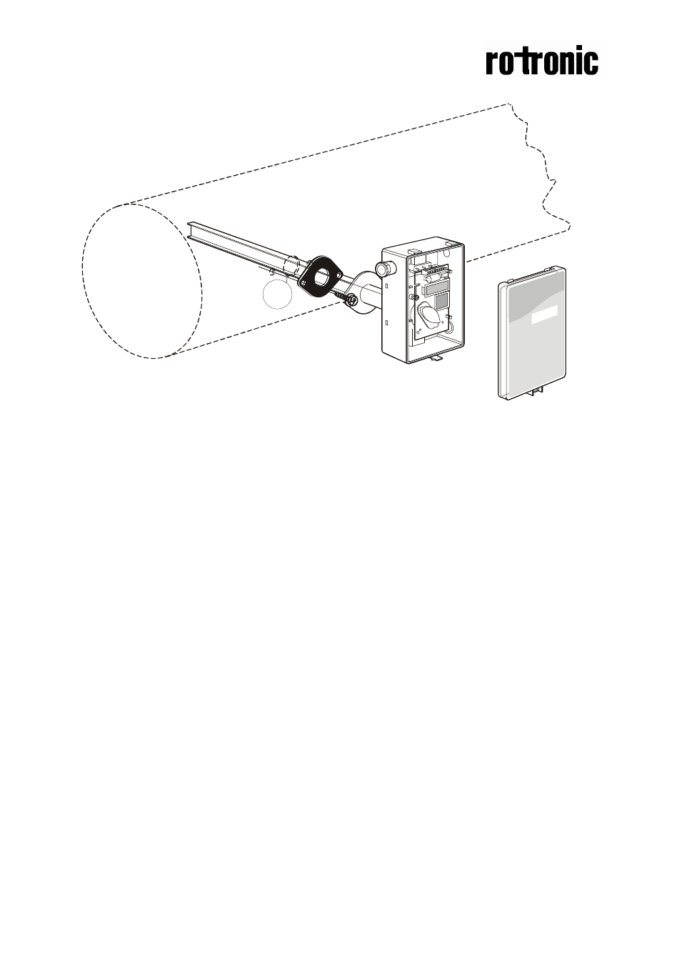
Figure 3 Mounting of the sensor to the ventilation duct
10
Hole with 25 mm diameter
11
Temperature sensor with 110 mm cable mounted in the sampling probe
Mounting Instruction
Since there might be a substantial pressure difference in duct mounting applications,
it is essential to avoid ambient air from suction into the duct mounting box. For
correct function it is indispensable that the sealing of the box cover, the cable entry
bushings, the cable feed through and the duct entrance are absolutely tight. The duct
entrance may need extra sealing paste in order to prevent leakage. The PCB must
be handed carefully and protected from electrostatic discharge.
1) Electrical cable entry: The box has a factory mounted cable entry bushing in
dimension PG9. Never feed more than one cable through each cable entry
bushing, or else gas might leak through!
2) Mounting the tube: Drill a hole (10) with 25 mm diameter (or 1 inch) for the
sampling probe and two holes with 4 mm diameter for the screws (5) into the air
duct and mount the tube (1) with the gasket (2). The sampling probe should be
mounted with the largest locking knob on top. The unit can be mounted with the
air coming from the left or right.
3) Attaching the sensor box is made to the sampling probe by a snap-in bayonet
fitting. Orient the box onto the sampling probe so that the box upside is on the
same side as the largest locking knob (3). When the probe is fitted into the
notches of the box, then turn the box clockwise until stop (see Figure 1). Position
1 indicates open where the box can be removed from the sampling probe. In
position 2 the box is locked to the probe
.
10