Part 2 – connecting the kdm-8206, Figure 2 rear view of kdm-8206 measuring module, Figure 2 – Kaman KDM-8206 User Manual
Page 5: Rear view of kdm-8206 measuring module
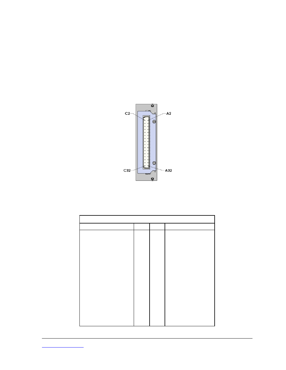
PART 2 – CONNECTING THE KDM-8206
All input, output, and synchronization connections to the KDM-8206 Measuring Module are at the
terminals of the Euro connector on the rear of the enclosure.
The Measuring Module is designed for insertion in a 3U/84HP rack enclosure. The rack provides
a mating Euro connector and input power supply. The sensor input is via a TBNC connector on
the rear panel of the rack. The output signal is a BNC coaxial connector also on the real panel.
Refer to the separate manual for rack details and operation. A Measuring Channel can be
operated independently of a rack or installed in a user provided rack if connected as detailed in
the table below.
Figure 2
Rear View of KDM-8206 Measuring Module
KDM-8206 Measuring Module Connections
Function
Pin C
Pin A
Function
+15 VDC in
2
2
+15 VDC in
NC 4
4
NC
- 15 VDC in
6
6
- 15 VDC in
NC 8
8
NC
Ground 10
10
Ground
NC 12
12
NC
V+ Out
14
14
V+ Out
V - Out
16
16
V - Out
NC 18
18
NC
NC
20
20
I Out High
NC
22
22
I Out Low
NC 24
24
Demodulator
Out
Ground 26
26
Ground
Synch Out
28
28
Synch In
Sensor Return
30
30
Sensor Return
Sensor Inactive Coil
32
32
Sensor Active Coil
Kaman Precision Products
PART NO: 860516-001
www.kamansensors.com
Last Revised: 6/20/2011
5