Part 1 – kdm-8206 description, Figure 1 kdm-8206 circuit, Figure 1 – Kaman KDM-8206 User Manual
Page 3
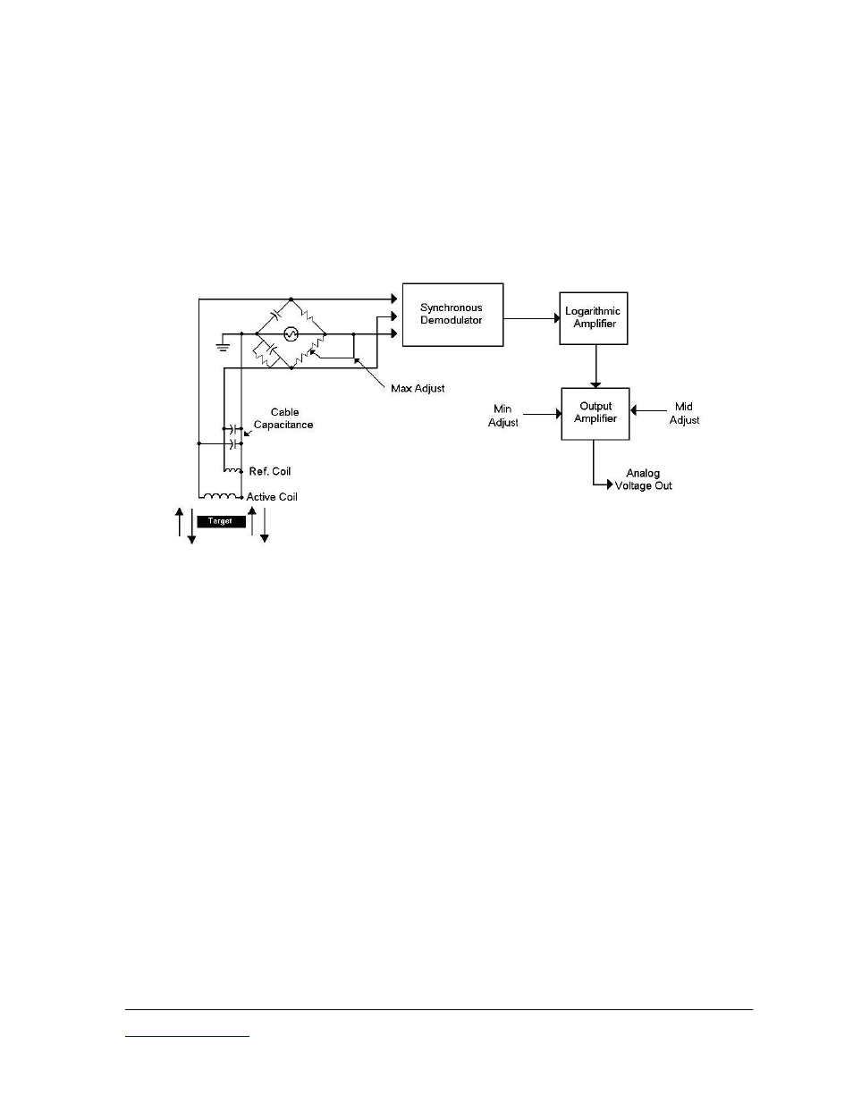
PART 1 – KDM-8206 DESCRIPTION
Kaman Precision Products’ Model KDM-8206 is a non-contact, linear, analog displacement
measuring system. The system operates on a traditional inductive bridge circuit. This easy-to-use,
versatile system can be utilized for precision static and dynamic measurements of conductive targets.
The sensor coil makes up one or two legs (depending on single or dual coil sensor) of a balanced
bridge network. As the target changes position within the sensor field, the bridge network senses
impedance changes in the sensor coil. These changes are converted to an analog voltage or
current signal directly proportional to target displacement.
Figure 1
KDM-8206 Circuit
KDM-8206 product is a replacement for the KDM-8200 series product and has many improved
features, but uses the same type enclosure and Euro connector. The MIN, MID, and MAX
adjustments were labeled Zero, Gain, and Linearity adjustment controls respectively in the KDM-
8200 systems.
A KDM-8206 Measuring Module is the signal conditioning electronics unit. It is packaged in a
Eurocard 3U by 7T enclosure.
A KDM-8206 Measuring Channel consists of two subassemblies: a sensor with either an integral
or a removable cable, and a Measuring Module. The Measuring Channel is preconfigured at the
factory for a particular sensor, cable length, target material, and measuring range. The KDM-
8206 Measuring Channel is a RoHS compliant, CE Marked design. To maintain the CE Mark, the
following precautions are necessary:
1. I/O cable length is limited to a maximum of 30 m (100 ft).
2. The Eurocard electronics are supplied with a cover over to protect the circuit from damage
due to Electrostatic Discharge (ESD). Removal of the cover makes the unit susceptible to
ESD damage and it must be handled accordingly.
Kaman Precision Products
PART NO: 860516-001
www.kamansensors.com
3. The electronics power and I/O must be isolated from the AC Mains and not subject to
transient over-voltages. That is, it must be powered by a D.C. secondary circuit that is
reliably grounded, capacitively- filtered, with peak-to-peak ripple less than 10% of the D.C.
component.
Last Revised: 6/20/2011
3