W.e. anderson div., dwyer instruments, inc – Dwyer 3ZV1 User Manual
Page 2
Instructions for Operation
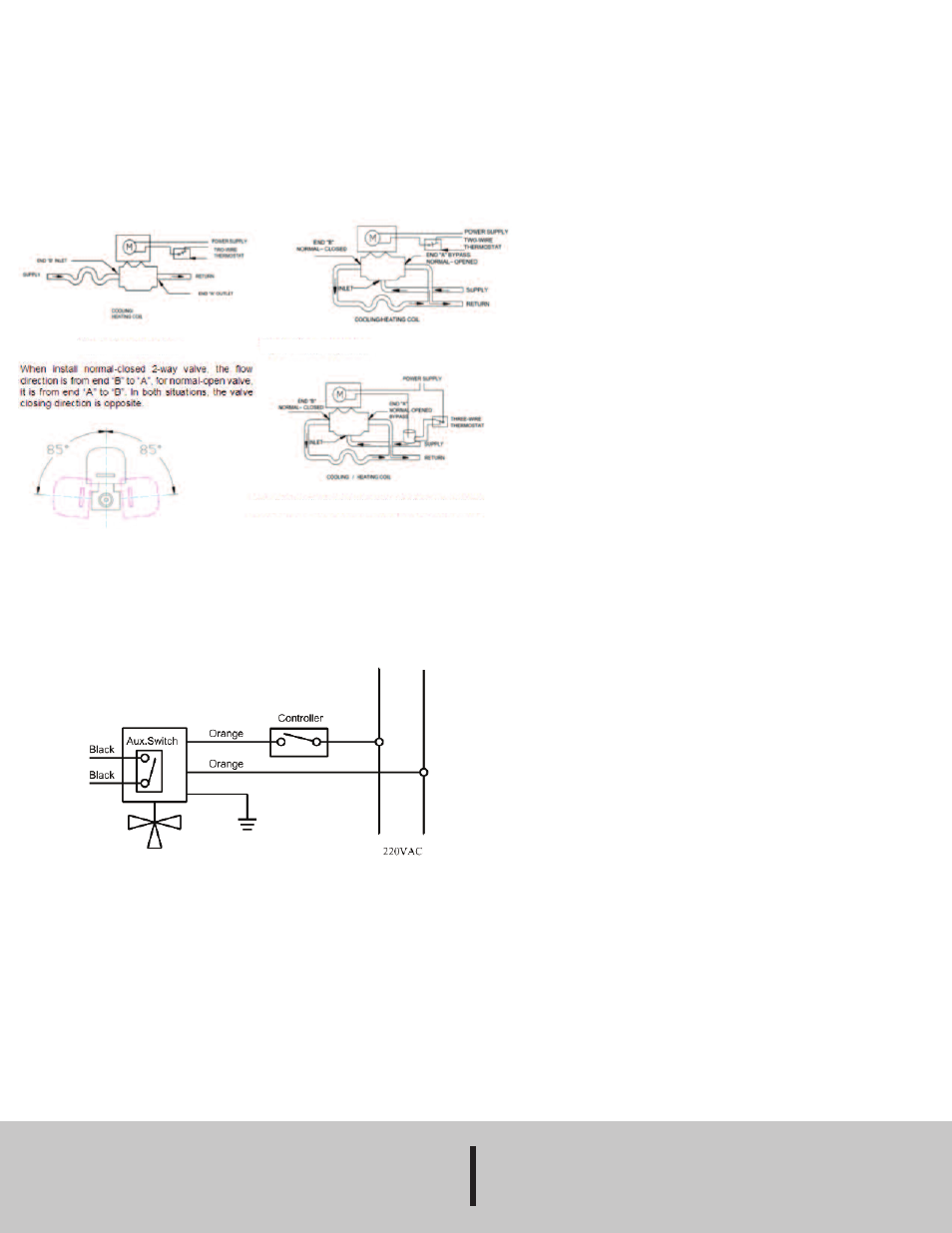
Normally-closed 2-way and diverting 3-way valve are installed as Figure 1, 2 and
3 shows. For high building, pressure –reducing valves should be installed on
branch pipes at ground floor.
Note: When the valve is mounted on a horizontal pipe, the angle must be
positioned less than 85°(see Figure 4).
When the valve is mounted on a vertical pipe, prevent from dripping.
Manual operating lever: Move the manual operating lever slowly and hold in the
retaining notch, and then the valve is in normal-opened position. When the valve is
first powered on, the lever goes back to the automatic position again.
When installing a diverting 3-way valve, end “B” is the supply to the coil, end “A” is
the by-pass. There is no mark for an inlet. End “A” and “B” are marked on the
bottom of the valve.
When the valve has an auxiliary micro switch, the wiring diagram is as follows:
MAINTENANCE
Upon final installation of the Series 3ZV1 Three-Way Zone Valves, no routine
maintenance is required. A periodic check of the system calibration is
recommended. The Series 3ZV1 is not field serviceable and should be returned if
repair is needed (field repair should not be attempted and may void warranty). Be
sure to include a brief description of the problem plus any relevant application
notes. Contact customer service to receive a return good authorization number
before shipping.
©Copyright 2014 Dwyer Instruments, Inc.
Printed in U.S.A. 6/14
FR # R2-443459-10 Rev. 1
Fig. 1 Two-way valve
Fig. 2 Three-way valve
Fig. 4
Fig. 3 Three-way valve with box change-over switch
W.E. ANDERSON DIV.,
DWYER INSTRUMENTS, INC.
P.O. BOX 358 • MICHIGAN CITY, INDIANA 46360 U.S.A.
Phone: 219/879-8000
www.dwyer-inst.com
Fax: 219/872-9057
e-mail: [email protected]