W.e. anderson div., dwyer instruments, inc – Dwyer EVA1 User Manual
Page 2
©Copyright 2005 Dwyer Instruments, Inc.
Printed in U.S.A. 12/05
FR# R2-443386-00
W.E. ANDERSON DIV., DWYER INSTRUMENTS, INC.
P.O. BOX 358 • MICHIGAN CITY, INDIANA 46361 U.S.A.
Phone: 219/879-8000
www.dwyer-inst.com
Fax: 219/872-9057
e-mail: [email protected]
Note: Actuator must be protected from dripping water. Damage
to internal elements and motor may occur. Do not cover actuator
with material that does not permit heat exchange.
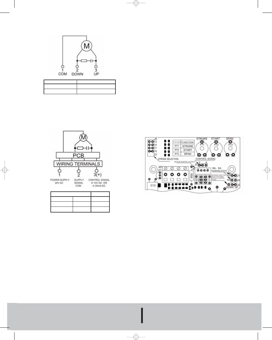
EVA1M WIRING DIAGRAM
OPERATION
1. The actuator is driven by a reversible synchronous motor with a
magnetic clutch. The motor can provide stable torsion at stopping
conditions due to the magnetic force created by the motor rotor
and the magnetic clutch. When power is taken away, the motor
will stop at its current position.
2. The signal of the proportional type actuator controls the
clockwise or counter-clockwise rotation of the motor.
3. EVA1M actuators can be jumper selected for 0.51, 0.59, 0.67
or 0.75 inch valve strokes. Factory stroke setting is 0.75˝.
4. The input control signal is jumper selectable between 0-10V or
4-20 mA DC. Factory setting is 0-10V DC input mode.
5. Direct (DA) or Reverse (RA) direction operation is also jumper
selectable. The two states are opposite of each other.
EVA1M PCB SETTING DIAGRAM
EVA1F WIRING DIAGRAM
TERMINALS
1-2
1-3
ACTUATOR ROD
DOWN EXTEND
UP CONTRACT
MAINTENANCE
The Series EVA1 Electric Actuator is not field serviceable and
should be returned if repair is needed (field repair should not be
attempted and may void warranty). Make sure to cut off power
supply when disconnecting the actuator from the valve. Contact
customer service to receive a return goods authorization number
before shipping. Be sure to include a brief description of the
problem plus any relevant application notes.
INPUT CONTROL SIGNAL
DA
INCREASE
DECREASE
RA
DECREASE
INCREASE
ACTUATOR
ROD
DOWN
UP
Bulletin V7 12/29/05 8:34 AM Page 2