Dwyer BCV User Manual
Bcv-1, Check valve - ball series, Components
Dwyer Instruments Inc.
P.O. Box 373, 102 Indiana Hwy. 212
Michigan City, IN 46361 USA
Tel. 219/879-8000 - Fax 219/872-9057
E-mail: [email protected] - Website: www.dwyer-inst.com
Check Valve - Ball Series
Characteristics
Working pressure at 20°C (73°F) water temperature:
- D20 - D63 (½”-2”): PN 16 bar (240 p.s.i.)
- D75 - D110 (2½”-4”): PN 10 (150 p.s.i.)
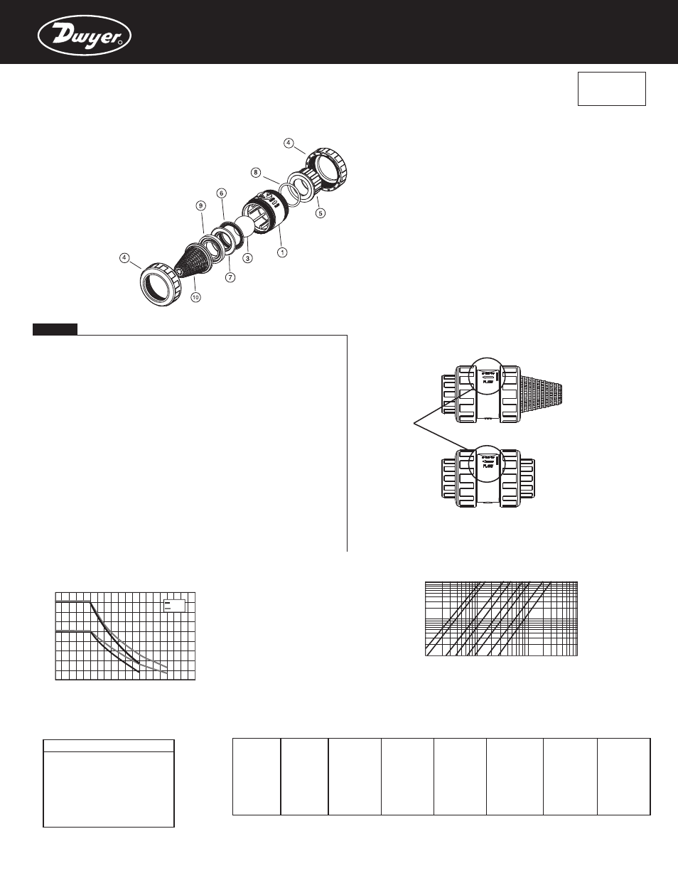
Description
1.
Body
PVC / CPVC
3.
Ball
PVC / CPVC
4.
Union nut
PVC / CPVC
5.
End connector
PVC / CPVC
6.
Closing ring
PVC / CPVC
7.
Body o-ring
EPDM / Viton®
8.
End connector o-ring
EPDM / Viton®
9.
Seal-carrier
PVC / CPVC
10. Screen
PP
Material
Components
Assembly Instructions
Solvent socket or threaded unions
Loosen the union nuts (4) and separate these and the end connectors (5) from the valve body. Pass
the pipe through the nuts and then place the bushes over the ends of the pipe. The solvent unions
should be glued onto the pipe using a PVC adhesive and pressure should not be applied to the
system until a drying period of at least 1 hour per 14.5 psi of working pressure has elapsed. In the
case of threaded unions, PTFE tape should be applied to the male threads. The pipes can now be
attached to the valve by hand tightening down the nuts.
Installation may be vertically and horizontally
WARNING: Minnimum return pressure: 0,2 bar (3 psi)
Foot valve
Use the screen instead of the end connector of the fluid entrance to transform the check valve into a
foot valve.
Foot valves are a particular type of check valves which are installed on the base of an aspiration pipe
of a pump to prevent the impulsion pipe from emptying.
The valve must be installed between the pump and the tank in order to let the fluid access the pump
and stopping it when returning to the tank. The entry of the valve is protected by a screen filter to
prevent the entry of unwanted elements which could exist in the tank or deposit.
• WE RESERVE THE RIGHT TO CHANGE ALL OR PART OF THE FEATURES OF THE ARTICLES OR CONTENTS OF THIS DOCUMENT, WITHOUT PRIOR NOTICE.
ENGLISH
E
D
IT
IO
N
:
1
2
-
2
0
0
6
R
20 years / water flow
Temperature
Pr
es
su
re
18
16
14
12
10
8
6
4
2
0
0 10 20 30 40 50 60 70 80 90
°C
32 50 68 86 104 122 140 158 176 194
°F
bar
psi
PVC
CPVC
270
240
210
180
150
120
90
60
30
0
PN 10
PN 16
D20- ½”
D25 - ¾”
D32 - 1”
D40 - 1¼”
D50 - 1
A
B
A
B
A
B
A
B
A
B
A
B
A
B
A
B
1.65 0.13
1.47
0.05
4.36
0.08
4.87
0.15
6.41 0.002
12.53
0.05
12.32
0.05
7.13
0.009
2.33 0.24
2.01 0.054
4.89
0.11
6.21
0.17
11.3
0.02
14.9
0.07
14.95
0.06
15.91
0.04
3.34 0.44
2.34
0.09
5.44
0.15
7.52
0.21
18.76 0.16
17.12
0.11
19.53
0.11
28.58
0.13
3.85 0.52
2.95
0.18
5.89
0.21
10.61
0.27
25.05 0.34
21.7
0.16
25
0.17
37.22
0.22
4.52 0.69
3.6
0.29
7.01
0.26
12.53
0.34
28.44 0.41
27.36
0.28
32.6
0.28
45.61
0.53
-
-
4.03
0.36
9.23
0.39
15.23
0.4
-
-
32.02
0.37
41.43
0.55
58.5
0.64
-
-
4.21
0.38
-
-
-
-
-
-
37.68
0.43
-
-
-
-
½”
D63 - 2”
D75 - 2½”
D90 - 3”
Cv
Kv
D20 - ½”
7
99
D25 - ¾”
9
128
D32 - 1”
22
308
D40 - 1¼”
32
453
D50 - 1½”
56
795
D63 - 2”
73
1040
D75 - 2½”
135
1932
D90 - 3”
193
2754
Pressure loss diagram
Check valve
Foot valve
Pressure / temperature diagramm
Relative flow chart
A= Flow (m³/h)
B= Pressure loss (bar)
Pressure loss diagram
FLOW
DIRECTION
Kv= l/min at 1 bar
Cv= GPM at 1 psi
Pr
es
su
re
l
o
ss
Flow
100
1.000
10.000
1
mca
(l/min)
10
26,4
264
2.642
(GPM)
15
psi
150
0
D
2
½
”
0
-
25
D
-
¾
”
D
32
1
”
-
-
D
40
1¼
”
D
½
”
50
-
1
D
63
-
2
”
5
D
7
-2
½
”
D
0
-
3”
9
0
Bcv-1