W.e. anderson div., dwyer instruments, inc – Dwyer ABFV User Manual
Page 4
©Copyright 2006 Dwyer Instruments, Inc.
Printed in U.S.A. 12/06
FR# R2-443533-00
Page 4
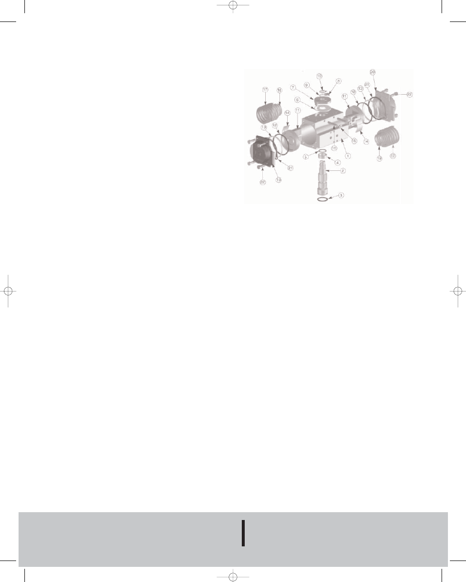
PNEUMATIC ACTUATOR PARTS LIST
1. Extruded aluminum housing
2. Nickel plated steel anti-blowout pinion
3. NBR 70 lower pinion O-ring
◊
4. PTFE pinion spacer ring
◊
5. NBR 70 top pinion O-ring
◊
6. PTFE cam spacer ring
◊
7. SS indicator cam
8. Nylon position indicator
9. SS pinion washer
10. Pinion snap ring
11. Die cast aluminum piston
12. Piston O-ring bushing
◊
13. PTFE antifriction ring
◊
14. PTFE piston thrust block
◊
15. SS stop bolt retaining nut
16. SS stop bolt
17. External spring*
18. Internal spring*
19. Die cast aluminum end cap (left)
20. Die cast aluminum end cap (right)
21. NBR end cap seats
22. SS end cap bolt
*spring return actuators only parts subject to wear. Please contact the
factory or your W.E. Anderson distributor for replacement kits.
MAINTENANCE
The Series ABFV Automated Butterfly Valves are not field
serviceable and should be returned if repair is needed (field repair
should not be attempted and may void warranty). Be sure to
include a brief description of the problem plus any relevant
application notes. Contact customer service to receive a return
goods authorization number before shipping.
PNEUMATIC ACTUATOR
NOTE: For optimal operation, 3PBV actuators should be run with a
supply of clean, lubricated air.
SPRING RETURN ACTUATORS
Air to PORT 2 (the right hand port) causes the actuator to turn CCW.
Loss of air to PORT 2 causes air to exhaust and the actuator turns
CW. This is the FAIL CLOSE operation.
DOUBLE ACTING ACTUATORS
Air to PORT 2 (the right hand port) causes the actuator to turn CCW.
Air to PORT 1 (the left hand port) causes the actuator to turn CW.
DISASSEMBLING STANDARD ACTUATORS
IMPORTANT: Before beginning disassembly, ensure that the air
supply to the actuator has been disconnected, all accessories have
been removed and that the actuator has been dismounted from the
valve.
1. Loosen the end cap fasteners (22) with a wrench (size varies
depending on actuator model). On the spring return actuator, alternate
3 to 5 turns on each fastener until the springs are completely
decompressed. Use caution in removing the cap since the springs are
under load until the fasteners are fully extended.
2. Remove the pinion snap ring (10) with a lock ring tool. The indicator
(7) may now be removed.
3. Turn the pinion shaft (2) CCW until the pistons are at the full end of
travel. Disengage the pistons (11) from the pinion. (NOTE: Low
pressure air--3 to 5 P.S.I. MAXIMUM--might be required to force the
pistons completely from the body.) Note the position of the pistons
before removing them from the actuator body. The part numbers of the
pistons are located on the side and should be right-side up on an
actuator with a standard orientation.
4. Remove the pinion through the bottom of the actuator. The actuator
is now completely disassembled. All replacement parts may now be
put in. W.E. Anderson recommends that all wear parts (3, 4, 5, 6, 12,
13, 14) be replaced before reassembly.
REASSEMBLING STANDARD ACTUATORS
IMPORTANT: Be sure that the actuator surfaces are free of grit
and scratches before reassembling.
1. Apply a light film of grease to all o-rings and the pinion before
replacing.
2. Put the pinion (2) back through the actuator with the flats of the
pinion shaft running parallel with the body.
3. When reassembling the actuator, make sure that the piston racks
are square to the actuator body and returned to their original
orientation. (NOTE: The normal operation of all PBV pneumatic
actuators is FAIL CLOSED. To change the orientation to FAIL OPEN,
rotate the racks 180º to create a reverse operation.)
4. When replacing springs in a spring return actuator, ensure that the
springs are replaced in their identical position in the end cap from
which they were removed. (NOTE: In some circumstances, you might
want to change the standard 80 pound spring set to fit your
application and available air pressure. Changing the spring sets on
3PBV pneumatic actuators requires no special tools. Please refer to
the spring combination torque chart in our catalog for the inner and
outer spring combinations that will allow you to operate with the spring
set that you desire.)
4. Seal the end caps with a petroleum lubricant and bolt to actuator
body.
5. Check the seal of the actuator by covering seal areas (pinion, end
caps) with soapy water and using low pressure air to the actuator to
ensure that no bubbles are produced.
PNEUMATIC ACTUATOR
W.E. ANDERSON DIV., DWYER INSTRUMENTS, INC.
P.O. BOX 358 • MICHIGAN CITY, INDIANA 46361 U.S.A.
Phone: 219/879-8000
www.dwyer-inst.com
Fax: 219/872-9057
e-mail: [email protected]
V-28 12/18/06 10:03 AM Page 4