W.e. anderson div., dwyer instruments, inc, Cv values break torques in inch-pounds – Dwyer BFV User Manual
Page 2
W.E. ANDERSON DIV., DWYER
INSTRUMENTS, INC.
P.O. BOX 358 • MICHIGAN CITY, INDIANA 46361 U.S.A.
Phone: 219/879-8000
www.dwyer-inst.com
Fax: 219/872-9057
e-mail: [email protected]
VALVE DISASSEMBLY
1. After removal of valve from the piping system, open the valve fully;
2. Remove the handle or actuator;
3. Remove the stem retaining pins;
4. Pull out the upper stem;
5. Pull out the bottom stem;
6. Remove the disc from the liner. Do not damage the disc edge;
7. Remove the liner;
8. If the valve has bushings and o-rings, remove by tapping with blunt instrument;
9. Inspect all components for wear and replace as required.
VALVE ASSEMBLY
1. Clean all reusable parts;
2. If valve has bushings and o-rings, tap them carefully;
3. Apply a lubricant or soapy solution compatible with elastomers to facilitate
assembly;
4. Insert liner into body by pressing it into the body evenly;
5. Insert disc in open position into liner. Make certain broached end of disc is at
the upper stem end of the body;
6. Coat the upper stem with a general purpose lubricant & install into body;
7. Install bottom stem;
8. Install retaining pins to both stems;
9. Install the operator;
10. Check assembly by opening & closing the valve several times;
11. Follow installation instructions for reinstalling the valve in the piping system.
MAINTENANCE
No regular maintenance or lubrication is required.
WARRANTY
The Series BFV Butterfly Valve is warranted from defects in materials and
workmanship for (1) year from the date of purchase. In the unlikely event the valve
should fail, the unit can be returned to the factory for warranty repair if the warranty
period has not expired. Contact our customer service department for an RGA
number and to set up the return.
LO
HAND LEVER “HL”
EPDM Seats
Service Pressure
50 psi
100 psi
150 psi
200 psi
PTFE Seats
Service Pressure
50 psi
100 psi
150 psi
200 psi
Size (inches)
Size (inches)
2
86
108
126
150
2-1/2
126
144
150
198
3
179
195
210
297
4
295
310
335
400
5
540
610
699
725
6
750
780
847
940
8
1440
1490
1549
1800
10
2466
2910
3360
3890
12
3510
4100
5560
7558
2
125
130
142
180
2-1/2
130
145
160
220
3
195
210
248
340
4
390
430
443
490
5
650
690
720
795
6
890
940
974
1020
8
1690
1710
1770
1890
10
3699
4365
5040
5835
12
5265
6150
8340
11367
DEGREE OPENING
Size
2˝
2-1/2˝
3˝
4˝
5˝
6˝
8˝
10˝
12˝
FULL OPEN
10°
0.1
0.2
0.3
0.5
0.8
2
3
4
5
20°
5
8
12
17
29
45
89
151
234
30°
12
20
22
36
61
95
188
320
495
40°
24
37
39
78
133
205
408
694
1072
50°
45
65
70
139
237
366
727
1237
1911
60°
64
98
116
230
392
605
1202
2047
3162
70°
90
144
183
364
620
958
1903
3240
5005
90°
135
220
302
600
1022
1579
3136
5340
8250
80°
125
204
275
546
930
1437
2854
4859
7505
Cv is the number of U.S. GPM of 60°F water that will pass through the valve with a 1 PSI
pressure drop.
Cv VALUES
BREAK TORQUES IN INCH-POUNDS
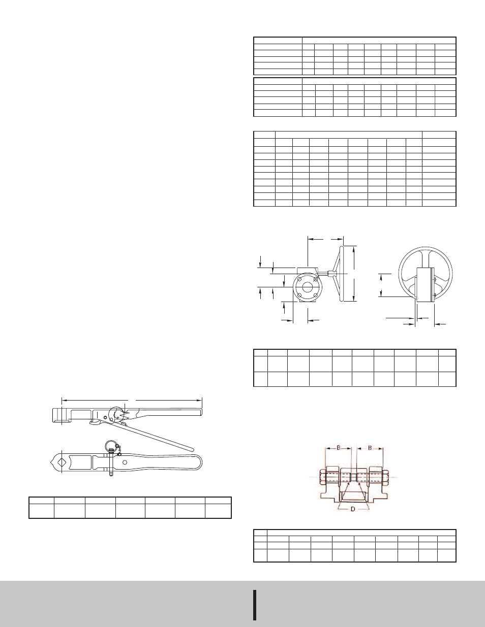
MANUAL GEAR “MG”
FIGURE 1
Size
LO
2˝
10-41/64
(270.27)
2-1/2˝
10-41/64
(270.27)
3˝
10-41/64
(270.27)
4˝
10-41/64
(270.27)
5˝
10-41/64
(270.27)
6˝
10-41/64
(270.27)
F
C
B
A
E
Ø
G
h1
g1
Size
8˝-
10˝
12˝
A
2-61/64
(75)
3-13/64
(81.36)
B
2-31/64
(63.10)
3-5/32
(80.17)
Ø
11-13/16
(300.04)
11-13/16
(300.04)
g1
2-49/64
(70.25)
2-49/64
(70.25)
h1
1/8
(3.18)
1/8
(3.18)
C
3-63/64
(101.20)
4-21/32
(118.27)
E
2-61/64
(75)
3-13/64
(81.36)
F
9-27/32
(250.03)
8-15/16
(227.01)
G
3-25/64
(86.12)
3-9/32
(83.34)
DIM
B
D
Valve Size (inches)
2
1-1/2
5/8
-11UNC
2-1/2
1-1/2
5/8
-11UNC
3
1-1/2
5/8
-11UNC
4
1-3/4
5/8
-11UNC
5
1-3/4
3/4
-10UNC
6
2
3/4
-10UNC
8
2
3/4
-10UNC
10
2-1/4
7/8
-9UNC
12
2-1/2
7/8
-9UNC
LUG RECOMMENDED FLANGE BOLT LENGTHS (Fig. 1)
HAND LEVER DIMENSIONS [in (mm)]
MANUAL GEAR DIMENSIONS [in (mm)]
©Copyright 2011 Dwyer Instruments, Inc.
Printed in U.S.A. 9/11
FR# R2-440860-50 Rev.1