Calibration s/w, Setting lamp setting point s/w – Dwyer VPT User Manual
Page 3
Adjustment of Potentiometer
The potentiometer is deigned to output a 12 mA signal when the
feedback lever is at 50%. In case of dislocation of the potentiometer,
please note the following before re-setting the potentiometer:
-Power must be turned off before adjusting the potentiometer.
-Be sure there is no remaining current on the PCB.
-Excessive force is unnecessary when disconnecting the potentiometer
from the PCB. Excessive force may cause damage to the transmitter.
1. Locate the potentiometer under the PCB and disconnect. Do not use
excessive force.
2. Unfasten the lock screw which locks the potentiometer gear and
remove potentiometer body from the lag-gear.
3. Fix the feedback lever at 50% and measure the resistance.
4. Rotate the pinion gear until resistance value reaches approximately
5K ohms.
5. After setting the resistance value, rotate the stopper to the normal
position and fasten the lock screw.
6. Reconnect the potentiometer to the PCB and reinstall the PCM onto
the Position Transmitter’s body.
Adjustment of Setting Points
The Series VPT Position Transmitter can be calibrated by either of the
following options.
1. 2 Point Setting: By setting the minimum and maximum points 0 and
100%, the values between the outputs are calculated and calibrated
automatically.
2. 5 Point Setting: By setting 5 points 0, 25, 50, 75, and 100%, the
outputs can be set accordingly. In general, a 5 point setting is much more
accurate.
Adjustment of Calibration
1. Input a 4 mA signal to the positioner in order to move the valve stroke
to its default position.
2. After the valve stroke reaches its default position, press the “4 mA”
button for approximately 3 to 4 seconds. The indicator light will light up,
indicating that the 4 mA position has been calibrated.
3. Please repeat the above steps for 8, 12, 16, and 20 mA settings for
the 5 point setting. For the 2 point setting, repeat the above steps only
for 20 mA.
Troubleshooting
1. VPT has no output signal
A. Check the input signal to the VPT.
B. Check power connection and polarity of terminals.
2. Input and output signals for the positioner differ greatly.
A. Check the input signal value and voltage. Insufficient voltage can
affect the input signal value.
B. Check the installation of the positioner. If the positioner is not properly
installed, reinstall properly using the positioner’s manual.
C. Reset positioner’s zero and span values. Inaccurate zero and span
settings can lower accuracy and linearity.
D. Check the installation of the VPT. If it is installed improperly, refer back
to installation section of manual.
3. Sudden change in VPT’s output signal value.
A. Make sure the VPT’s lever is placed at 50%. If not, the VPT needs to
be re-installed and adjusted to place lever at 50%.
B. Adjust the potentiometer. The potentiometer’s resistance should be at
approximately 10K ohms at the 50% point.
MAINTENANCE/REPAIR
Upon final installation of the Series VPT, no routine maintenance is
required. The Series VPT is not field serviceable and should be returned
if repair is needed. Field repair should not be attempted and may void
warranty.
WARRANTY/RETURN
Refer to “Terms and Conditions of Sales” in our catalog and on our
website. Contact customer service to receive a Return Goods
Authorization number before shipping the product back for repair. Be
sure to include a brief description of the problem plus any additional
application notes.
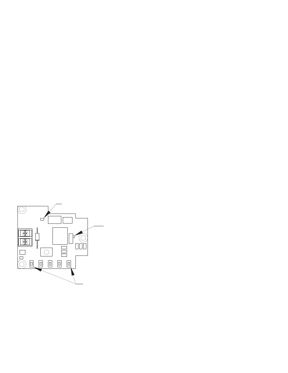
Calibration S/W
4m
A
8m
A
12
m
A
16
m
A
20
m
A
Setting Lamp
Setting point S/W
5-P
O
IN
T
2-POINT