Proximity controls – Dwyer VPS User Manual
Page 2
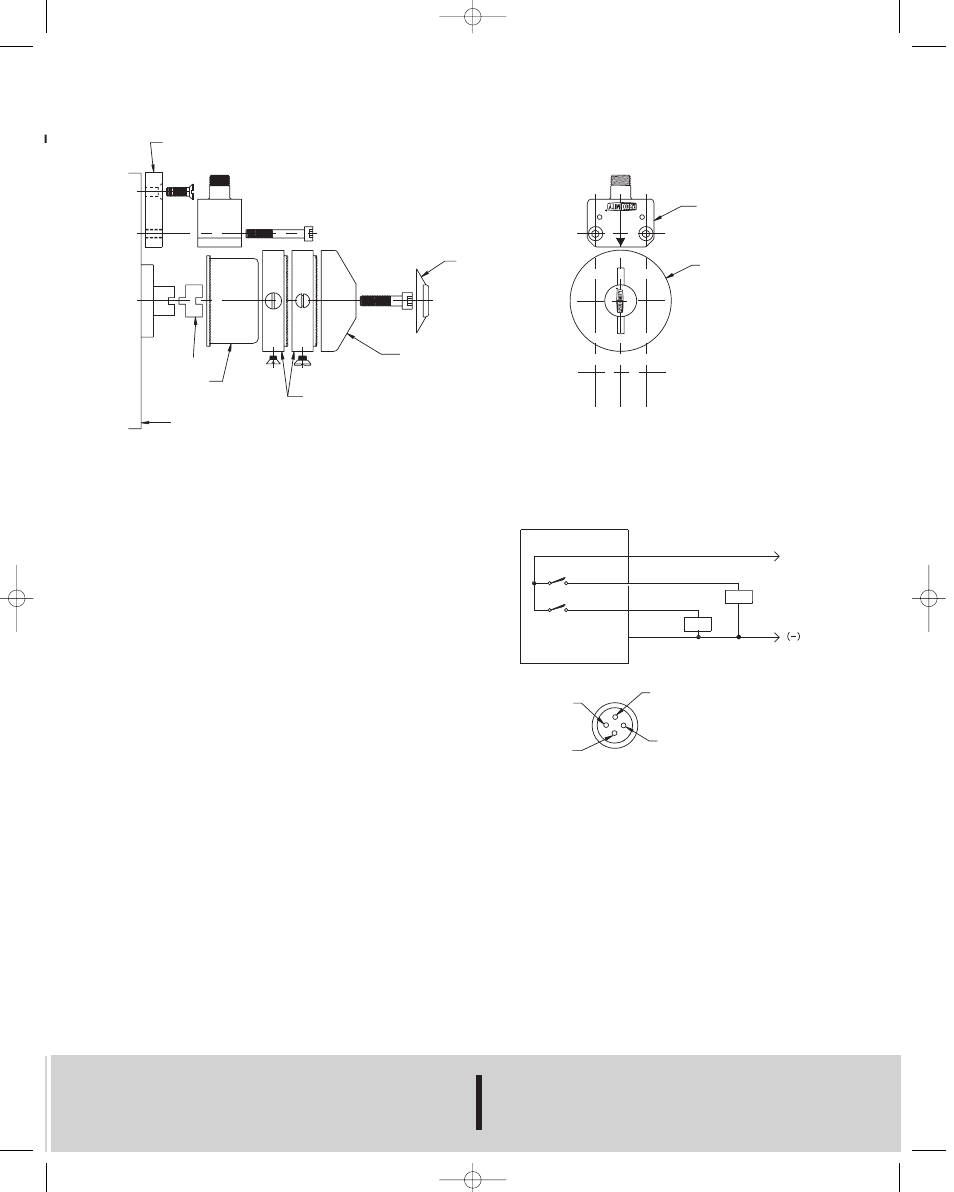
NAMUR C BRACKET
COUPLING
COLLAR
NAMUR ACTUATOR DIMENSIONS
NAMUR A HOLE PATTERN 30mm X 80mm, SHAFT HEIGHT 20mm
NAMUR B HOLE PATTERN 30mm X 80mm, SHAFT HEIGHT 30mm
NAMUR C HOLE PATTERN 30mm X 130mm, SHAFT HEIGHT 30mm
TARGET RINGS
COVER
FLOW INDICATOR
MODEL No. VPS
MODEL No. P1
(+)
MODEL VPS2411
1 BROWN
4 BLACK
2 WHITE
3 BLUE
SW1
GRN LED
SW2
RED LED
PIN 4 BLACK
PIN 1 BROWN
PIN 3 BLUE
PIN 2 WHITE
HOUSING CONNECTOR
NOTE:
1. WIRE COLORS ARE FOR VIP82 QUICK DISCONNECT CABLE
LOAD
LOAD
INSTALLATION PROCEDURE:
1. Fasten the Series VPS to the actuator with the appropri-
ate fasteners (M5, 10-24, 10-32). For Namur C actuators
you must first attach the Namur C bracket to the actuator.
2. Attach the coupling to the actuator shaft for Namur A &
C actuators only.
3. Attach the collar to the actuator shaft or coupling.
4. Install one stainless steel flat head screw (two if it is a
dual sensor installation) into each of the target rings and
plug the other holes with the plastic screws or plugs. Slide
the target rings over the collar and adjust as appropriate for
open and closed position. NOTE: Bottom target energizes
the red LED and the top target energizes the green LED.
5. Place the cover onto the top target being careful to align
for proper flow indication and secure with M6 x 16 fastener
for Namur B actuators or M6 x 25 fastener for Namur A & C
actuators.
6. Insert flow indicator to complete assembly or install cou-
pling to maintain VDI/VDE 3845 dimensions if accessories
such as a positioner are to be installed.
PROXIMITY CONTROLS
Phone: 218/739-3364
www.proximitycontrols.com
A DIVISION OF DWYER INSTRUMENTS, INC.
Fax: 218/739-2734
e-mail: [email protected]
1431 STATE HIGHWAY 210 E • FERGUS FALLS, MN 56537 U.S.A.
©Copyright 2002 Dwyer Instruments, Inc
Printed in U.S.A. 11/02
FR# 85-443220-00
WIRING DIAGRAM
INSTALLATION DRAWING
F-65 10/30/02 3:06 PM Page 2