Dwyer instruments, inc – Dwyer DDC User Manual
Page 2
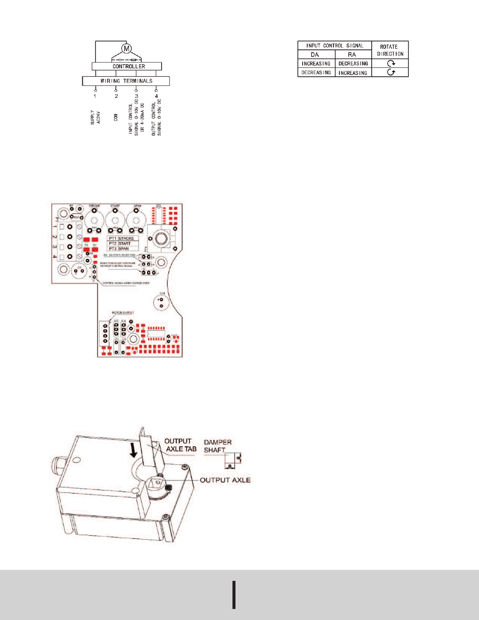
WIRING DIAGRAM
Set Up
• Set jumper J1 or J2 to proper selection for reverse or direct acting. See
Chart 1: Actuator Action above for more detail.
• Set jumper J3 for Voltage or Current input control signal.
• Set jumper J4 for actuator direction on loss of control signal.
• Potentiometer PT1 adjusts the stroke of the actuator.
Square shaft installation
Before installation, the aluminum gasket should be put into the hole of
Output Axle. Fix with square damper shaft. The rotating angle of the
actuator can be set by internal potentiometer. The match between
working range and feedback signal is automatically done by the actuator.
CHART 1: ACTUATOR ACTION
MAINTENANCE
Upon final installation of the Series DDC Non-Spring Return Direct
Coupled Actuator, no routine maintenance is required. A periodic check
of the system calibration is recommended. The Series DDC is not field
serviceable and should be returned if repair is needed (field repair
should not be attempted and may void warranty). Be sure to include a
brief description of the problem plus any relevant application notes.
Contact customer service to receive a return good authorization number
before shipping.
a = .4˝ (10 mm)
or
.5˝ (13 mm)
DWYER INSTRUMENTS, INC.
Phone: 219/879-8000
www.dwyer-inst.com
P.O. BOX 373 • MICHIGAN CITY, INDIANA 46360, U.S.A.
Fax: 219/872-9057
e-mail: [email protected]
©Copyright 2014 Dwyer Instruments, Inc.
Printed in U.S.A. 5/14
FR# R3-443451-40 Rev. 2