Dwyer 1205A-5 User Manual
Page 3
Ambient Air Measurements
When testing for CO in rooms, make sure the meter has been switched on
in OUTDOOR fresh air before the meter is calibrated.
After the countdown is finished and the meter is correctly set up, take the
meter into the room to be tested, make sure its pump is on and use the
probe to draw in ambient air for the meter to measure.
• Only switch on the meter in OUTDOOR, FRESH AIR.
• Do not exceed the meter’s internal temperature operating range.
• Do not put the meter on a hot surface.
• DO NOT expose yourself and others to dangerous levels of CO.
PRINTING TEST INFORMATION
An optional accessory for the 1205A-5 is an infrared thermal printer. Read
the manual supplied with the printer prior to operation. Connection to the
1205A-5 is detailed below:
• Infrared thermal printer – this does not require a cable to trans-
mit the data but uses an infrared (IR) link similar to a TV remote
control. The IR emitter is positioned on the top of the 1205A-5
and the bottom of the printer. Ensure they are pointing at each
other and within 3 feet (1 meter), with no obstructions in the
way. Data may be lost if transmission is interrupted. Keep the
1205A-5 pointing at the printer until the printout has finished.
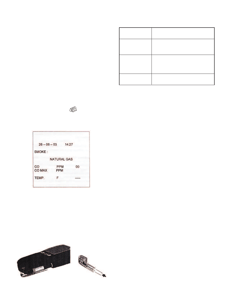
During combustion tests the 1205A-5 will print data on request. With the
meter showing the MAIN DISPLAY press and current data will be
sent to the printer.
The display will show “PRINTING” until data transmission is complete.
Below is an example of a typical printout:
AFTER USING THE METER
After using the meter to test appliances, remove its probe from the flue –
IT WILL BE HOT – and let it cool. Do not put the probe in water which will
be sucked into the meter, damaging its pump and sensors.
When the meter readings return to ambient levels, switch it off. The meter
counts down from 30 before switching off with the pump running to self-
clean its sensors.
Empty the water trap and check filter prior to storage and next use.
PROBLEM SOLVING
If any problems are not solved with these solutions, contact an authorized
repair center.
RECALIBRATION AND SERVICE
Although sensor life is typically more than two years, the meter should be
re-calibrated and serviced annually to stop any long-term sensor or elec-
tronics drift or accidental damage.
Local regulations may require more frequent calibration.
MAINTENANCE
Upon final installation of the Model 1205A-5 Handheld CO Analyzer and
the companion receiver, no routine maintenance is required. A periodic
check of the system calibration is recommended. The Model 1205A-5 is
not field serviceable and should be returned if repair is needed (field repair
should not be attempted and may void warranty). Be sure to include a brief
description of the problem plus any relevant application notes. Contact cus-
tomer service to receive a return goods authorization number before ship-
ping.
ELECTROMAGNETIC COMPATIBILITY
European Council Directive 89/336/EEC requires electronic equipment not
to generate electromagnetic disturbances exceeding defined levels and
have adequate immunity levels for normal operation. Specific standards
applicable to this meter are stated below.
As there are electrical products in use pre-dating this Directive, they may
emit excess electromagnetic radiation levels and, occasionally, it may be
appropriate to check the meter before use by:
Use the normal start up sequence in the location where the meter will be
used.
Switch on all localized electrical equipment capable of causing interfer-
ence.
Check that all readings are as expected. A level of disturbance is accept-
able.
If not acceptable, adjust the meter’s position to minimize interference or
switch off, if possible, the offending equipment during your test.
• CO sensor error (----)
• Batteries not holding
charge
• Meter not running on
mains adapter
• Meter was stored in a cold environment and
is not at normal working temperature.
• CO sensor needs replacing.
• Batteries exhausted.
• AC charger not giving correct output.
• Fuse blown in charger plug.
• Meter does not
respond to flue gas
• Water trap drain plug not installed.
• Particle filter blocked.
• Probe or tubing blocked.
• Pump not working or damaged with contam-
inants.
• Erratic temperature
readings or 000 on
display
• Temperature plug reversed in socket.
• Faulty connection or break in cable or plug.
Figure 3 - Water Trap and Filter