Dwyer SSR-15 User Manual
Page 2
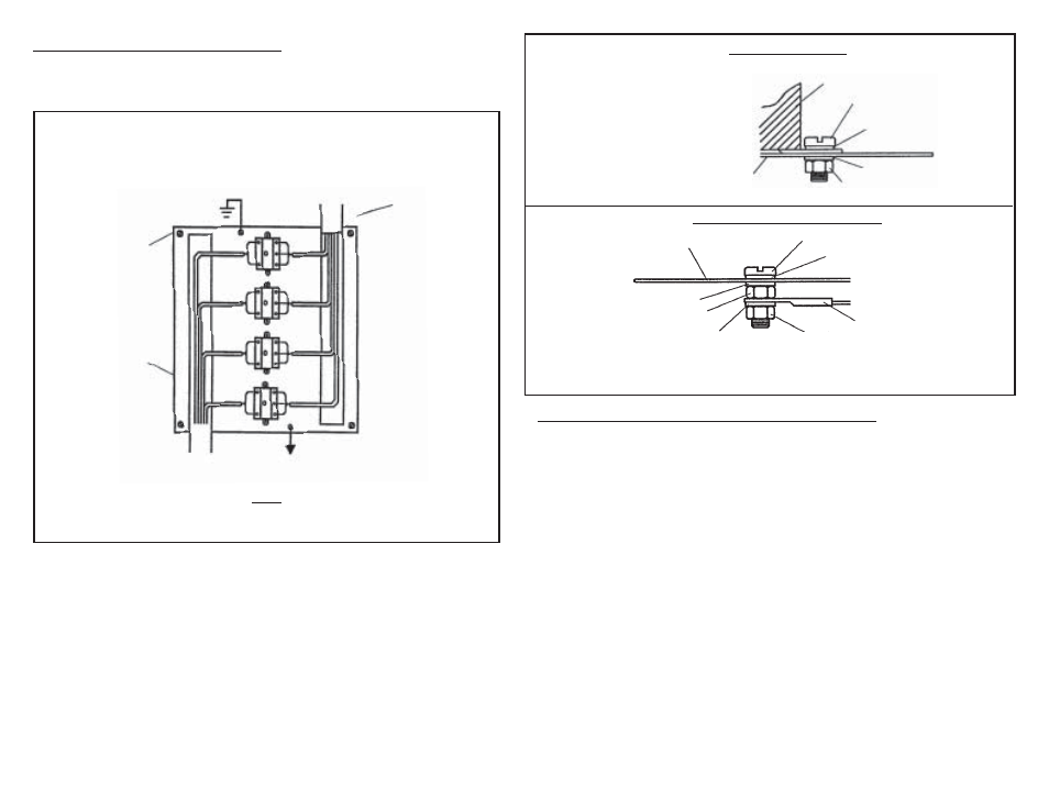
2. Mounting and Enclosure Considerations:
Field wiring of intrinsically safe circuits is to be segregated from non-
intrinsically safe wiring by use of suitable barriers, separate wireways or
trays (See Fig. 2). Wire insulation to be .010", minimum.
Intrinsically safe and non-intrinsically safe connection points should be
located sufficiently apart to prevent any possibility of bypassing or miswiring
during installation or servicing of equipment.
The enclosure shall contain a cautionary statement as follows: “CAUTION:
ANY SUBSTITUTION OF COMPONENTS MAY IMPAIR INTRINSIC
SAFETY”.
The SSR mounting bracket must be grounded to insure intrinsic safety.
Resistance between bracket and ground electrode should be below one
ohm. (See Fig. 3 and Fig. 4 for recommended selection of grounding
hardware and refer to Article 250 of the National Electrical Code for methods
and practices.)
B.
C.
D.
A.
3. Installation of Sensor Switch and Running of Field Wiring:
A. It is expected that the installation will be in accordance with Article 504 of the N.E.C.,
ANSI/NFPA 70 and/or C.E.C. Part 1*.
*Note: This is a CSA requirement. C.E.C. = Canadian Electrical Code.
B. The nature of the sensor switch must be that it is a non-voltage-producing, essentially
resitive device, containing no energy-storing components. (Simple Apparatus -flow
switches, level switches, pressure switches.)
C. The conductors of the intrinsically safe circuit should be sealed in a rigid metal conduit
at the point where the wiring enters the hazardous area. The wiring and contacting
device should be such that conductive dusts in the area will not close the circuit in
place of the contacts.
D. Hazardous area field wiring will store energy due to distributed capacitance and
inductance in proportion to its length. It is therefore recommended that the characteris-
tics (available from the manufacturer) of the cable be known and judged against the
length of run and atmosphere of exposure. The conservative chart on the next page is
presented as a requirement in determining the limits of reactance for signal loops in
the hazardous area wiring for the SSR series.
E. Whenever possible, the actual measured parameters should be used in making the
determination of allowable length.
F. Shielded cable is not required; but if used in the application, the shield must be returned
to ground - the same as the SSR mounting bracket.
G. Non-intrinsically safe wiring cannot be run in conduit or open raceways together with
intrinsically safe wiring.
Fig. 3. Unit Mounting Detail
* Note:
Lockwashers to be internal
or external tooth-type.
SSR-15
#10 Screw
* #10 Lockwasher
#10 Nut
Mounting Plate
* #10 Lockwasher
Fig. 4. Mounting Plate Grounding Detail
Mounting Plate
Screw
* Lockwasher
* Lockwasher
* Lockwasher
Nut
Nut
Terminal Lug
Notes:
1. Grounding Hardware to be #8 or larger and Stainless Steel.
2. * Lockwashers to be internal or external tooth-type.
Earth Ground
(2 Places)
Common
Earth Ground
Mounting Plate
Non-Intrinsically
Safe Wiring
Intrinsically Safe
Wiring to Sensors
Located in Hazardous
Area
Resistance to Gnd.
must be less than 1
ohm from mounting
screw or bracket to
earthing member to
insure integrity.
Fig. 2.
Multiple SSR units Grouped on
Common Earth-Grounded Mounting Plate
Located in Non-Hazardous Area
Note:
All intrinsically safe wiring must be segregated from non-intrinsically
safe wiring and shall have a minimum insulation thickness of .010”.