Proximity controls – Dwyer LTC User Manual
Page 2
INSTALLATION INSTRUCTIONS
MOUNTING
The control unit should be mounted in an area free from vibration and the
temperature should not exceed 125°F (52°C). Consideration should be
given to mounting the unit where indicator lights will be visible to the nec-
essary personnel, and wiring may be easily installed to the probe and
other machinery.
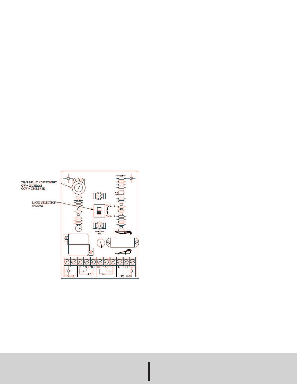
LOGIC SELECTOR
This jumper determines when the output relay actuates and de-actuates.
The following summarizes the operation with the jumper at each position.
Position 1: Relay energizes when probe is in the vertical
position.
Relay de-energizes when probe is in the tilted
position.
Position 2: Relay energizes when probe is in the tilted
position.
Relay de-energizes when probe is in the vertical
position.
Figure 1: CONTROL UNIT CIRCUIT
PROBE INSTALLATION
The probe should be suspended using a fixed support, such as a mount-
ing bracket and S-hook, at a position where it will easily intercept the bulk
material at the desired indication point. There must be a free flow of
material both to and away from the probe. In some installations, it is nec-
essary to install a baffle or shield above the probe assembly to protect it
from product surges.
MAINTENANCE
The Series LTC Tilt Probe Control Units are not field serviceable and
should be returned if repair is needed (field repair should not be attempt-
ed and may void warranty). Be sure to include a brief description of the
problem plus any relevant application notes. Contact customer service to
receive a return goods authorization number before shipping.
PROXIMITY CONTROLS
Phone: 219/879-8000
www.dwyer-inst.com
A DIVISION OF DWYER INSTRUMENTS, INC.
Fax: 219/872-9057
e-mail: [email protected]
P.O. BOX 373 • MICHIGAN CITY, INDIANA 46360, U.S.A.
©Copyright 2014 Dwyer Instruments, Inc.
Printed in U.S.A. 4/14
FR# R6-443489-00 Rev. 1