Dwyer PS User Manual
Page 2
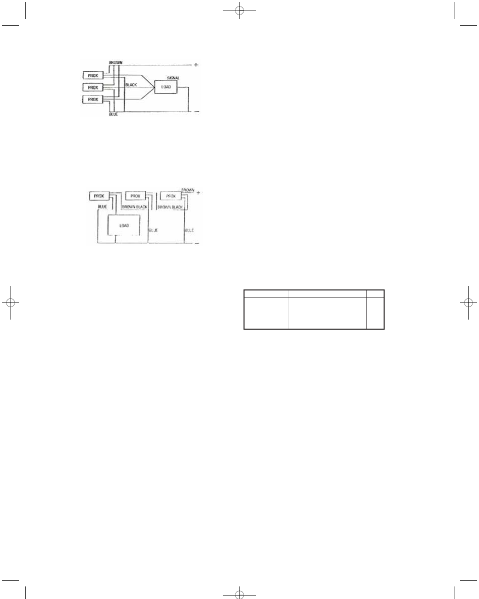
Multiple Units: Series
The maximum number of DC sensors connected in series is limit-
ed by the supply voltage (V supply), the voltage drop across a
closed switch (V switch) and either the minimum working voltage
of the switch or minimum working voltage of the load, whichever is
greater (V min).
The diagram above shows a typical series configuration of PNP
sensors. For NPN types, swap the blue for brown wire and recon-
nect.
SENSITIVITY ADJUSTMENT
Inductive Switches
Inductive PSI sensors are not adjustable.
Capacitive Switches
Install the capacitive PSC sensor in its final position. Remove the
black cover screw to gain access to the adjustment potentiometer.
Turn the adjusting potentiometer clockwise to increase sensitivity
or counterclockwise to reduce sensitivity. For example, the range
and sensitivity of capacitive sensors can be adjusted to tune out
the sidewall of a plactic container or glass window of a signt glass
such that the level of liquid, granules or powders on the other side
of the plastic or glass can be detected.
For this application tune out the sight glass or wall with the con-
tainer empty, detune the sensor so it cannot see the window or
wall. Then test the settings by introducing the target material
inside the container. Caution should be taken with materials that
leave a residue inside the container as this may be sensed.
NOTE: To maintain the IP65 rating on capacitive sensors, it is
imperative that the black cover screw be replaced after adjust-
ment.
GENERAL INFORMATION
LED Indicators
Most Proximity sensors are fitted with indicator lights (LED’s) at
the cable end. The LED indicates the state of the switch output.
Maximum Voltage
The maximum voltage of DC proximity sensors is 30 V. It is some-
times forgotten that a rectified 24 VAC supply has a peak value of
1.4 X the AC RMS value (34V).
NOTE: These switches should be installed by competent person-
nel only. Please check wiring and supply voltages before switch-
ing on. If there are any technical questions regarding installation
or application of Proximity sensors please contact the technical
sales department.
A-800 DC Proximity Switch Test Unit
The A-800 is fitted with two PP3 batteries ready for use. This unit
will test most 3 wire DC proximity switches PSI (metal sensing),
PSC (most materials), the magnet sensing Detector (DT), photo-
electrics or ultrasonics.
Standard color coding for 3 wire Proximity switches is
Brown=Positive (+), Black=Load, Blue=Negative (–). Note: Some
universal DC switches can vary. Follow the maufacturer’s wiring
instructions.
Testing Instructions
Connect the switch to the A-800. Place a suitable target in front of
the switch. If it is functioning correctly, the test unit will give audio
and visual indication showing that the switch operates and indicat-
ing functionality of the switch according to the chart below.
A-800 DC TEST UNIT
If the Proximity switch does not give such feedback when correct-
ly connected to the tester, it has probably failed. NOTE: The A-800
will not test 2 wire AC or DC switches.
LED Functions
Green I/O LED
Switch connected and unit on
Red (Battery) LED
Battery low indicator
PNP or NPN LED
Indicated switch type
Further Information:
Proximity is a Division of Dwyer Instruments, Inc. For further infor-
mation, a copy of our latest catalog, other products or details con-
cerning our nearest distributor please call our sales office.
SWITCH TYPE
PNP N.O.
PNP N.C.
NPN N.O.
NPN N.C.
LED
PNP
PNP
NPN
NPN
BUZZER & LED ON WHEN
Target in range
Target not in range
Target in range
Target not in range
E-81-PS:PS bulletin 2/4/10 8:05 AM Page 2