Power and signal connections, Not connected – Alicat MC Series Mass Flow Controller User Manual
Page 8
8
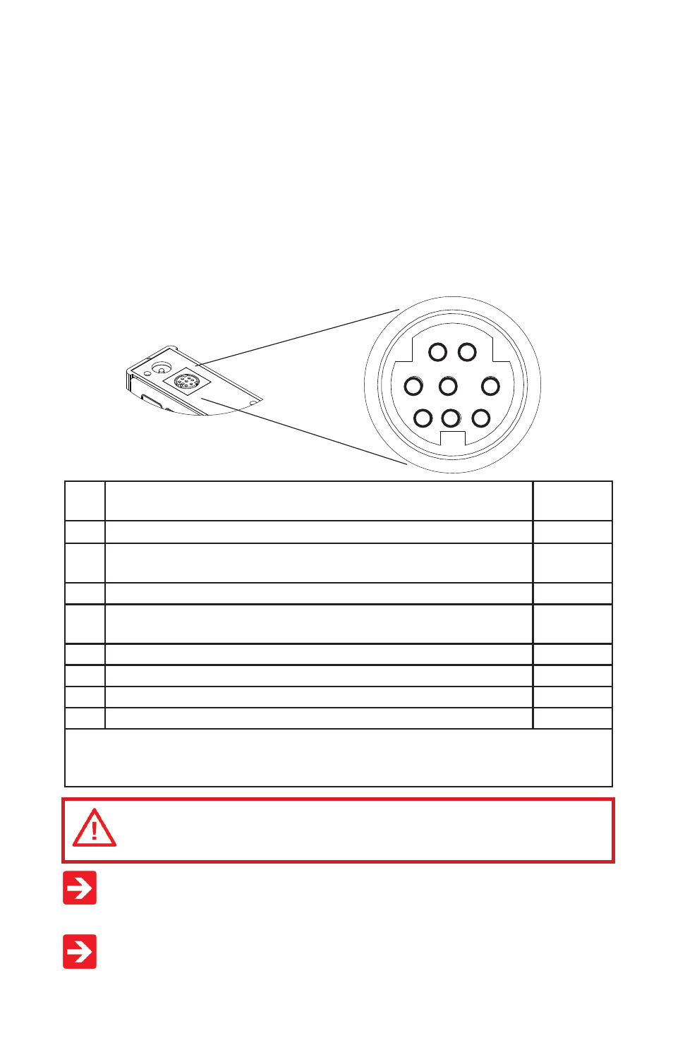
POWER AND SIGNAL CONNECTIONS
Power can be supplied to your controller through either the power jack (power jack
not available on CSA/ATEX approved devices) or the 8 pin Mini-DIN connector.
An AC to DC adapter which converts line AC power to DC voltage and current as
specifi ed below is required to use the power jack.
Small Valve controllers require a 12-30Vdc power supply with a 2.1 mm female
positi ve center plug capable of supplying 250 mA. NOTE: 4-20mA analog output
requires at least 15 Vdc.
Large Valve controllers require a 24-30 Vdc power supply with a 2.1 mm female
positi ve center plug capable of supplying at least 750mA.
Standard 8 Pin Mini-DIN Pin-Out
Pin Functi on
Mini-DIN
cable color
1
Not Connected
(or opti onal 4-20mA Primary Output Signal)
Black
2
Stati c 5.12 Vdc [or opti onal Secondary Analog Output (4-20mA,
5Vdc, 10Vdc) or Basic Alarm]
Brown
3
Serial RS-232RX (receive) Input Signal
Red
4
Meters/Gauges = Remote Tare (Ground to Tare)
Controllers = Analog Set-Point Input
Orange
5
Serial RS-232TX (send) Output Signal
Yellow
6
0-5 Vdc (or opti onal 0-10 Vdc) Output Signal
Green
7
Power In (as described above)
Blue
8
Ground (common for power, communicati ons and analog signals)
Purple
Note: The above pin-out is applicable to all the fl ow meters and controllers with the
Mini-DIN connector. The availability of diff erent output signals depends on the opti ons
ordered. Opti onal confi gurati ons are noted on the unit’s calibrati on sheet.
CAUTION! D� ��� ������� ����� �� ���� 1 ������� 6 �� ���������
������ ��� �����!
It is common to mistake Pin 2 (labeled 5.12 Vdc Output) as the standard 0-5 Vdc
analog output signal. In fact Pin 2 is normally a constant 5.12 Vdc that refl ects
the system bus voltage and can be used as a source for the set-point signal.
For 6 Pin Locking Industrial Connector, DB9 and DB15 pin-outs see pages 72
to 84. For PROFIBUS pin-outs see page 70.
1
2
3
4
5
6
7
8