Alicat Local SetPoint Module User Manual
Page 4
2
CAUTION: D
O
NOT
CONNECT
POWER
TO
PINS
1
THROUGH
6
AS
PERMANENT
DAMAGE
CAN
OCCUR
!
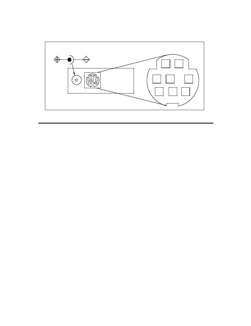
Figure 1. Pin Out Diagram
7
8
1
2
3
4
5
AC/DC Adapter Jack
6
Pin
Function
DC-61 (optional) Color Code
1
4-20mA Output Signal
Black
2
5.12 Vdc or Auxiliary Output
Brown
3
RS-232 Input Signal
Red
4
Set Point In
Orange
5
RS-232 Output Signal
Yellow
6
0-5 Vdc (or 0-10 Vdc) Output Signal
Green
7
Power In
Blue
8 Ground
(common)
Purple