Table 1: model number decoder, Dry contacts figure 3 – Advanced Protection XDS User Manual
Page 5
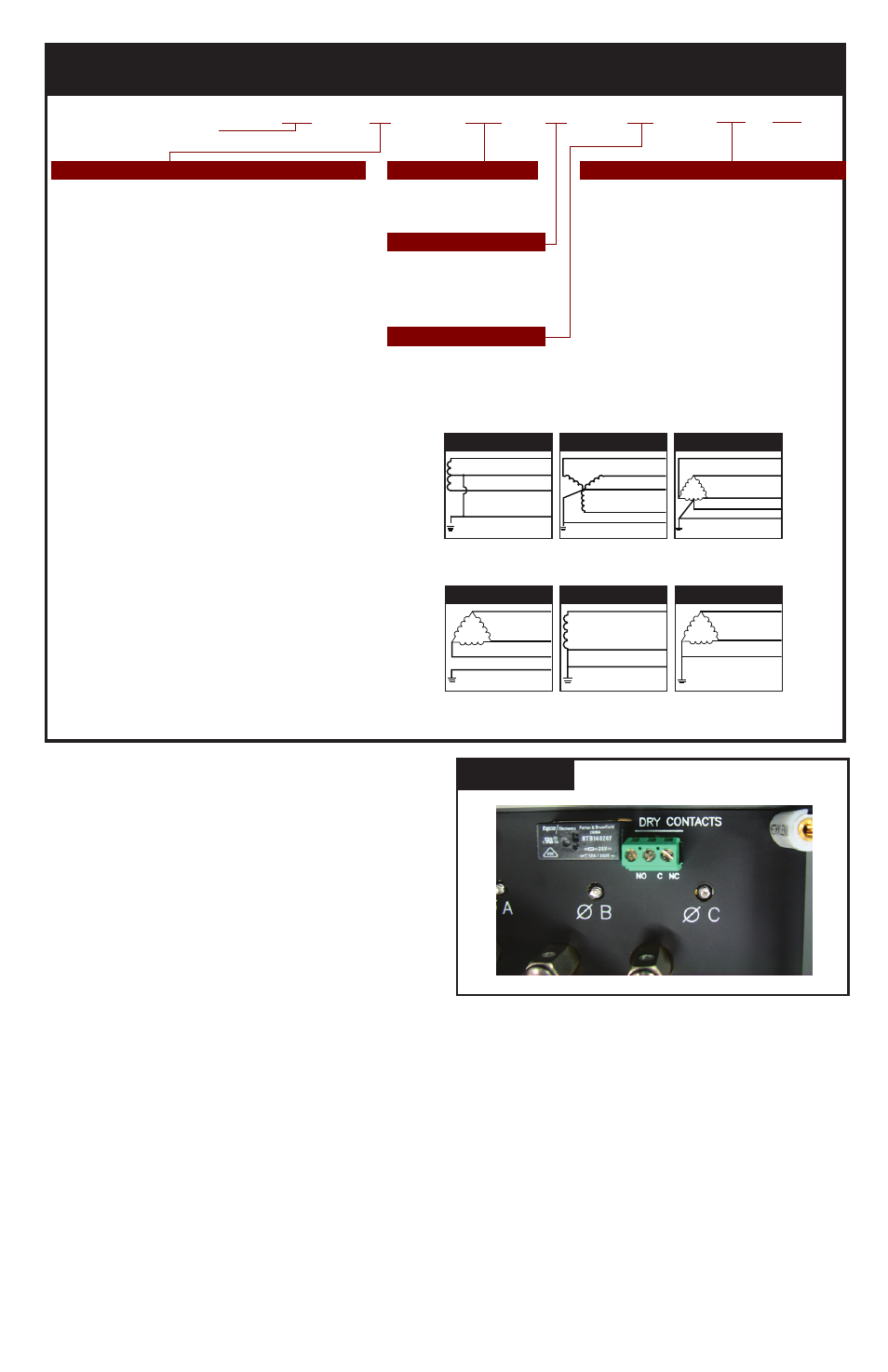
A Terminal Block includes one set of Normally
Open (N.O.) and Normally Closed (N.C) contacts.
This is shown in Figure 3.
Wire Size: 30 - 12 AWG; 18 AWG Recommended.
Torque: 0.5N - m or 5lbf - in.
A typical application using a Normally Closed
configuration would connect to one set of the N.C.
and Common terminals. During an inoperative
condition, the SPDs Dry Contact would change
state from Normally Closed to Open. We generally
suggest the Normally Closed configuration
because it will detect a wiring defect, such as cut
wire(s), where N.O. will not.
Please note:
Dry Contacts are designed for low voltage or
control signals only.
Maximum switching current is 5A. Maximum
switching voltage is 240V DC or AC. Higher
energy applications require additional relay
implementation outside the SPD.
An optional Remote Monitor accessory is
available to provide visual and audible status.
The Remote Monitor will consume the set of Dry
Contacts.
Optional Flush Mount Installation
Considerations
The XD is approximately 4” deep. The unit will not
mount flush unless there is as least 4” of depth
clearance. The XD is not designed to mount flush
on a typical 2 x 4 stud wall.
Back Flange Mounting: Mount as close as
possible to protected panel. Create a wall opening
slightly larger than 6 3/4” tall x 6 1/16” wide. See
drawing. Configure a robust backing plate inside
the wall cavity 3 15/16” from the wall face such
that the SPD is supported from its back. Note the
mounting holes on the back flange. Also note that
the XD weighs 5 lbs. Be careful not to drop the
SPD into the wall.
5
Transient Eliminator
Voltage Code for Electrical System Model Family
Options
TE
02
XDS
20
4X
A
A = Audible Alarm & Dry Contacts,
Form C, 240V, 5A
R = Remote Display on 4’ cable
S = Remote Display with Surge Counter
T = Remote Display with N-G LED
U = Remote Display with N-G LED and
Surge Counter
Type 2 SPD Bearing cUL Mark
Delete Options
L = Delete L-N Protection (reduces kA rating)
G = Delete L-G Protection (reduces kA rating)
N = Delete N-G Protection (reduces kA rating)
J = Delete Noise Filter
10
=
100kA/Phase
15
=
150kA/Phase
20
=
200kA/Phase
XDS = External Mount SPD
Standard Modes
Common North American Systems:
01 = 240/120V Split Phase - 1Ø, 3W+Grnd, (Fig 1)
02 = 208Y/120V Wye - 3Ø 4W+Grnd, (Fig 2)
03 = 240/120V High Leg Delta (B High), (Fig 3)
04 = 480Y/277V Wye - 3Ø 4W+Grnd, (Fig 2)
05 = 480V Delta - 3Ø 3W+Grnd, (Fig4) & HRG Wye
08 = 600Y/347V Wye - 3Ø 4W+Grnd, (Fig2)
4X =
NEMA 4X
Non-Metallic
(size 6"x6"x4")
Enclosure Rating
Figure 1
Figure 2
Figure 3
SPLIT
2 Hots, 1 Neu, 1 Grnd
HI-LEG DELTA (B High)
3 Hots, (B HIGH),
1 Neu, 1 Grnd
WYE
3 Hots, 1 Neu, 1 Grnd
Hot (BLK)
Hot (BLK)
Neutral (WHT)
V
V
}
}
Ground (GRN)
}
Phase A (BLK)
Phase B (BLK)
Neutral (WHT)
Phase C (BLK)
Ground (GRN)
A
C
N
V
B
Phase A (BLK)
Phase B (ORNG)
Neutral (WHT)
Phase C (BLK)
Ground (GRN)
}
V
Figure 4
Figure 5
Figure 6
SINGLE POLE
1 Hot, 1 Neu, 1 Grnd
DELTA & HRG WYE
3 Hots, 1 Grnd
CORNER GROUND
DELTA (B grounded)
2 Hots, 1 Grnd
V
}
Neutral (WHT)
Hot (BLK)
Ground (GRN)
Phase A (BLK)
Phase C (BLK)
Phase B (BLK)
Ground (GRN)
}
V
Phase A (BLK)
Phase C (BLK)
Ground (GRN)
V
}
Surge Current Rating
Other Available Systems - Confirmation encouraged:
15 = 254/127V Split Phase - 1Ø 3W+Grnd (Fig 1)
18 = 480/240V Split Phase, or Two legs of Wye (Call)
21 = 220Y/127V Wye - 3Ø 4W+Grnd (Fig 2)
41 = 520Y/300V Wye - 3Ø 4W+Grnd (Fig 2)
42 = 415Y/240V Wye - 3Ø 4W+Grnd (Fig 2)
43 = 400Y/230V Wye - 3Ø 4W+Grnd (Fig 2)
44 = 440Y/250V Wye - 3Ø 4W+Grnd (Fig 2)
51 = 480V B Corner Grnd Delta, 3Ø 3W+Grnd (Fig 6)
06 = 240V Delta - 3Ø 3W+Grnd (Fig 4)
61 = 240V B Corner Grnd Delta, 3Ø 3W+Grnd (Fig 6)
07 = 380Y/220V Wye - 3Ø 4W+Grnd (Fig 2)
09 = 600V Delta - 3Ø 3W+Grnd (Fig 4) & HRG Wye
(Available: 50kA, 100kA)
91 = 600V B Corner Grnd Delta, 3Ø 3W+Grnd (Fig 6)
(Available: 50kA, 100kA)
11 = 120V Single Phase (Fig 5)
12 = 240V Single Phase (Fig 5) - Not split phase
13 = 127V Single Phase (Fig 5)
14 = 300V Single Phase (Fig 5)
16 = 277V Single Phase (Fig 5)
17 = 480V Single Phase (1 Hot, 1 Neu, 1 Grnd) (Fig 5)
TABLE 1: MODEL NUMBER DECODER
Do not create model numbers from this chart as all features are not available on all models
Remote Display
Suffix
DRY CONTACTS
Figure 3