Disassembly procedure flowchart, Chapter 3 47 – Acer 3000 User Manual
Page 55
Chapter 3
47
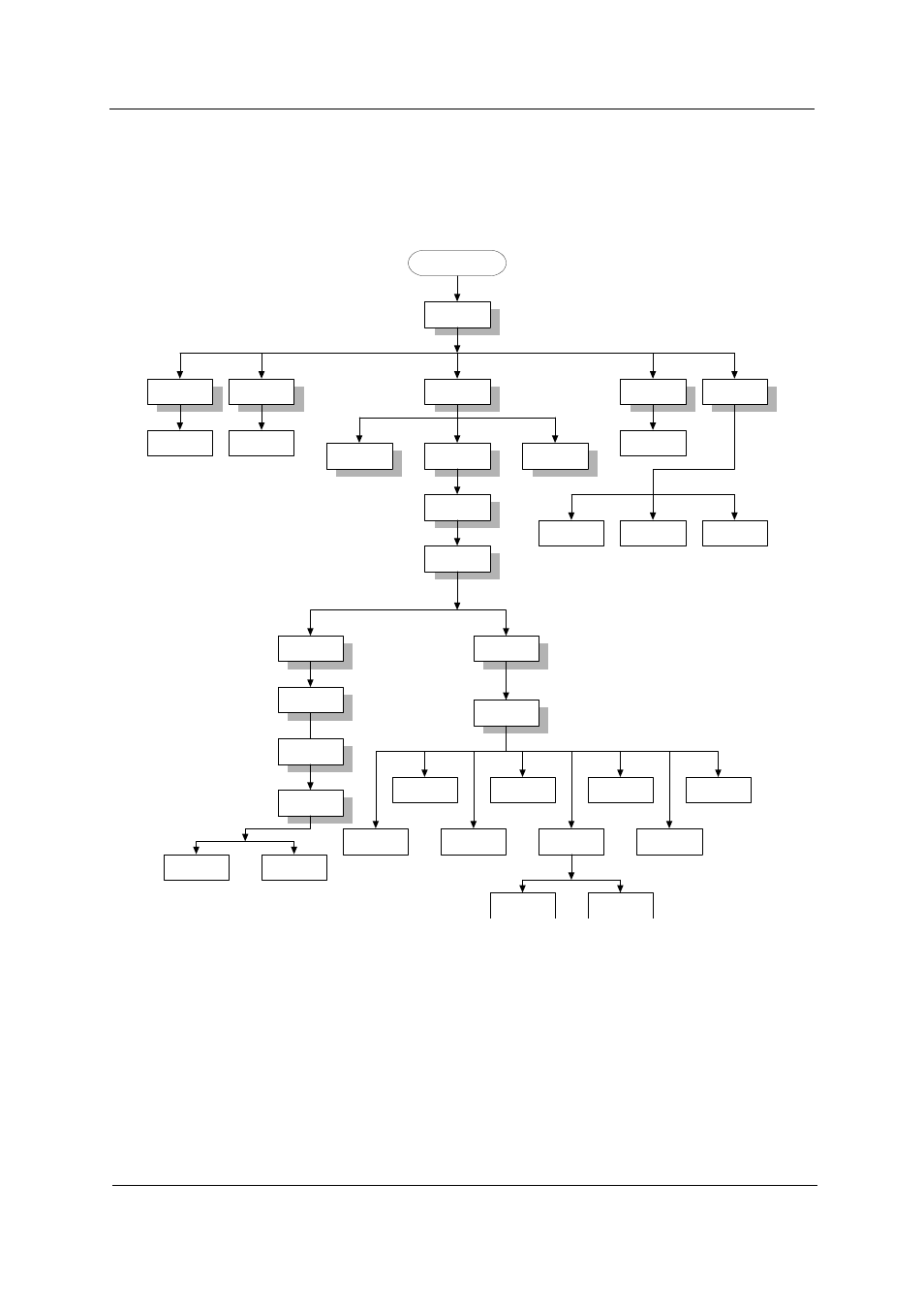
Disassembly Procedure Flowchart
The flowchart on the succeeding page gives you a graphic representation on the entire disassembly sequence
and instructs you on the components that need to be removed during servicing. For example, if you want to
remove the system board, you must first remove the keyboard, then disassemble the inside assembly frame in
that order.
Start
Battery
HDD Door
Middle Cover
ODD Module
HDD Module
Hx2
Fx2
LCD Module
Sx4
ODD Board
ODD Bracket
Keyboard
Hx2
Mx3
Main Unit
Assembly
Front Bezel
Logic Upper
Assembly
Sx19
Hx2
Ux3
Logic Lower
Assembly
Dimm Door
Memory
Hx2
Ox4
Function Key
Board
PCI Door
Wireless LAN
Card
Hx2
Hx3
ODD
Ax4
Hx1
Hx1
Main Board
CPU
Dimm
HDD
Bracket
4-in-1 Card
Rearder
Modem/
Bluetooth
Combo Card
Smart Card
Reader
Thermal
Module
Top Cover
Shielding
Fx2
Ex4
Tx2
Dx3
Hx2
Hx1
Touchpad
Shielding
Qx4
Touchpad
Board
Touchpad
Holder
Hx4
Touchpad
Touchpad
Cable (FFC)
Antenna Line
Modem Cable
Cx4
- Aspire 5741ZG (2345 pages)
- Aspire 5741ZG (313 pages)
- TravelMate 5330 (14 pages)
- Extensa 7230 (86 pages)
- AOD257 (1810 pages)
- AO753 (374 pages)
- AO533 (4 pages)
- AOD255 (299 pages)
- AO522 (1810 pages)
- Aspire EC-471G (10 pages)
- Aspire V5-531G (2484 pages)
- Aspire M3-581TG (3478 pages)
- Aspire M3-581TG (11 pages)
- Aspire M3-581PTG (10 pages)
- Aspire 8950G (378 pages)
- Aspire EC-471G (11 pages)
- Aspire V5-571PG (3604 pages)
- Aspire E1-571 (308 pages)
- Aspire E1-521 (11 pages)
- Aspire S5-391 (11 pages)
- Aspire S5-391 (111 pages)
- Aspire M5-581TG (10 pages)
- Aspire M5-581TG (11 pages)
- Aspire V3-471G (362 pages)
- Aspire V3-471G (11 pages)
- Aspire M5-481TG (11 pages)
- Aspire 9420 (109 pages)
- Aspire 9520 (123 pages)
- 3280 (106 pages)
- 4600 (128 pages)
- Aspire 1300 (96 pages)
- 4330 (198 pages)
- TravelMate 3250 (98 pages)
- 1450 (99 pages)
- 2420 (108 pages)
- 310 (2 pages)
- 310 (130 pages)
- 3690 (123 pages)
- 5010 (113 pages)
- 3250 (124 pages)
- 5560 (112 pages)
- 5230 (176 pages)
- 420 series (78 pages)
- 3200 Series (90 pages)