Rj-45 twisted pair port pinouts – Allied Telesis Layer 3 Gigabit Ethernet Switch x600-24Ts/XP User Manual
Page 67
x600 Layer 3 Gigabit Ethernet Switch Installation Guide
67
RJ-45 Twisted Pair Port Pinouts
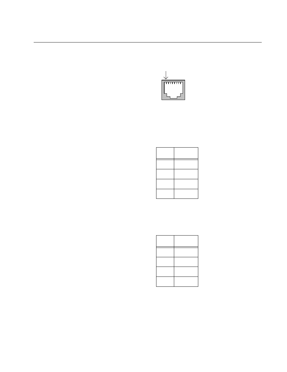
Figure 31 illustrates the pin layout of an RJ-45 connector and port.
Figure 31. RJ-45 Connector and Port Pin Layout
Table 10 lists the pin signals when a port is operating in the MDI
configuration at 10 or 100 Mbps.
Table 11 lists the pin signals when a port is operating in the MDI-X
configuration at 10 or 100 Mbps.
The MDI/MDI-X setting is established automatically when a port is set to
Auto-Negotiation. If a port’s speed and duplex are set manually, the MDI/
MDI-X setting defaults to the MDI-X setting.
Table 10. MDI Pin Signals - 10 or 100 Mbps
Pin
Signal
1
TX+
2
TX-
3
RX+
6
RX-
Table 11. MDI-X Pin Signals - 10 or 100 Mbps
Pin
Signal
1
RX+
2
RX-
3
TX+
6
TX-
Pin 1