Ar ch ive d, Includes dates before 5/05) – Seametrics EX100-200 Series v.1 User Manual
Page 4
Piping. For best results, the EX sensor should be in-
stalled with at least ten diameters of straight pipe
upstream and five downstream. Cer tain extreme situations
such as par tially-opened valves are particularly difficult
and may require more straight diameters upstream. The
101 and 201 sensors are supplied with a 1-1/2" male
pipe thread fitting. The 115 and 215 sensors have a 2”
NPT thread, for compatability with the 2” isolation valve.
Any fitting which provides the matching NPT female thread
may be used. The installation procedure compensates
for differences in height of the fitting.
Horizontal is the preferred installation orientation, since it
improves low-flow per formance and avoids problems with
trapped air. Bottom, top, and ver tical pipe installations
are all acceptable if required by the piping layout.
Immersion. The 100/200 Series standard sensors are
not designed for continuous underwater operation. If this
is a possibility, as in a flooded vault, a unit modified for
immersion should be specified.
Fitting Installation. First cut a minimum 1-3/4" hole in
the pipe. If possible, measure the wall thickness and write
it down for use in depth setting, below. Then install the
threaded fitting (saddle, weldolet, etc.) on the pipe.
Page 2
Caution: These flow sensors are not
recommended for installation down-
stream of the boiler feedwater pump
where installation fault may expose the flow
sensor to boiler pressure and temperature.
Maximum recommended temperature is 130
°F
(Plastic), 200
°F (Metal).
INSTALLATION
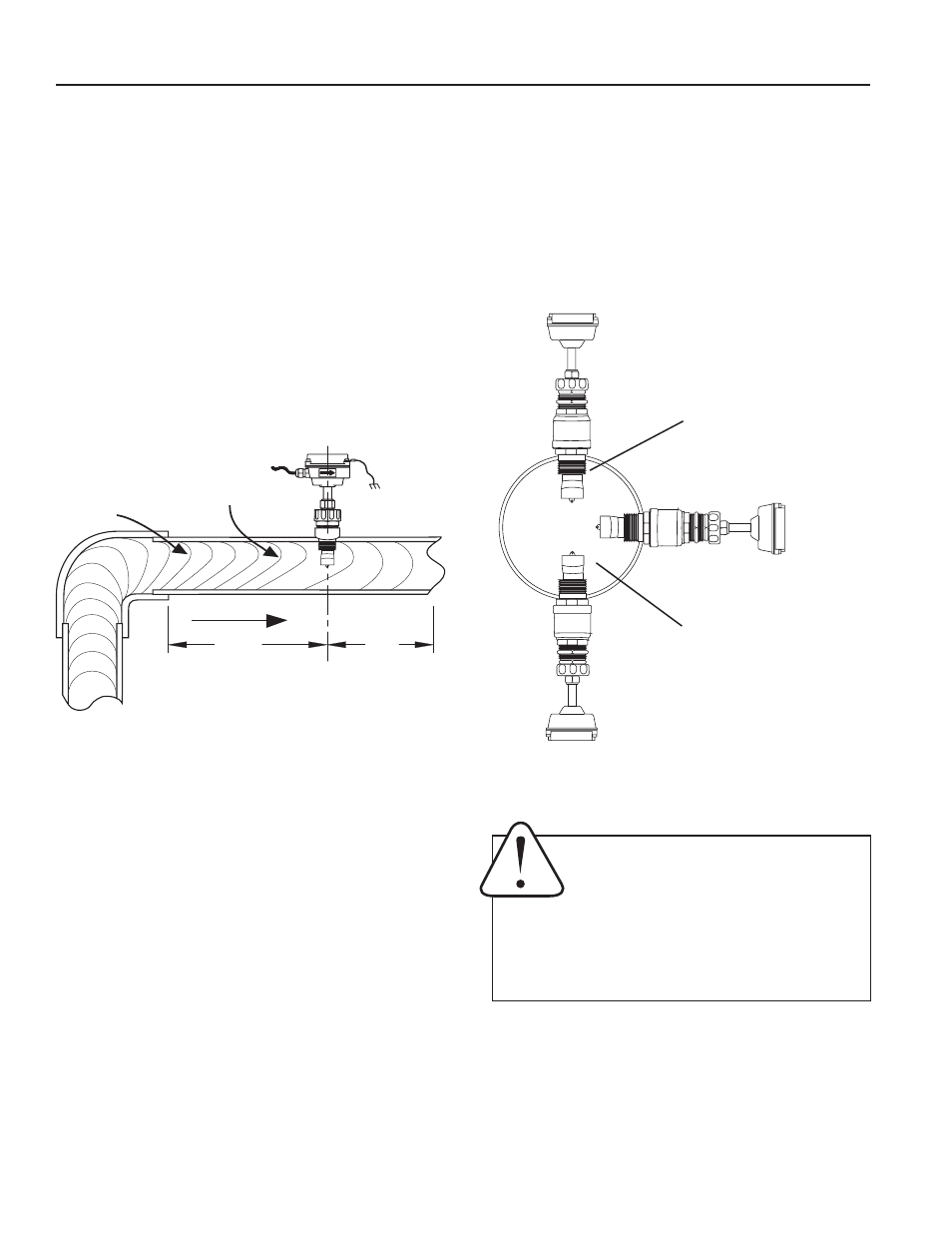
DISTORTED FLOWS
Distorted
Flow Profile
Faster Flow
Causes Meter
To Read High
FLOW
10X
Diameter Minimum
5X
Diameter
Minimum
Fair
(Unacceptable position
if air is present)
Best
Position
Fair
(Unacceptable position if
fluid contains sediment)
POSITIONING THE METER
Meter Installation. Remove the threaded adapter from
the sensor. Using a thread sealant, install the adapter in
the pipe fitting.
Do not overtighten. Slide the meter through
the adapter fitting. Engage the locking collar threads and
turn until the collar stops, about 1-1/2 to 2 turns.
AR
CH
IVE
D
(Includes Dates Before 5/05)