NSi Industries DZS100BP User Manual
Page 4
15
INSTALLATION INSTRUCTIONS
1. Remove unit from enclosure by pushing the inside tab
(located near the outside hasp) to the right. Swing
unit to left and remove.
2. Five combination 1/2” and 3/4” knockouts are provid-
ed on this enclosure. Remove the 1/2” (inner) knock-
out by inserting a screwdriver in the slot provided and
pound screwdriver handle with a hammer. Remove
knock-out with pliers and smooth hole edges with file
and knife if necessary. When the 3/4” outer knockout
is required, place screwdriver in groove and pound
screwdriver handle with hammer.
Remove loose
knock-out with pliers and smooth hole edges with file
or knife if necessary.
3. When attaching conduit to enclosure, exercise care to
align and support conduit in order to prevent unnec-
essary stress on enclosure.
4. Reinstall unit by reversing step 1 above and connect
wires according to wiring diagram on inside case
label.
GROUNDING
National Electrical Code requires that grounding must be
continuous and in proper electrical contact in all ground-
ing conductors, metallic conduits and grounding termi-
nals. When using metal conduits, install the proper size
approved grounding bushings. The minimum size copper
grounding conductors must be #10 AWG if the circuit
breaker or fuse is 30 or 40 amp, #12AWG if 20 amps,
and #14 AWG if 15 amp.
NOTE: Do not use top entry for wiring
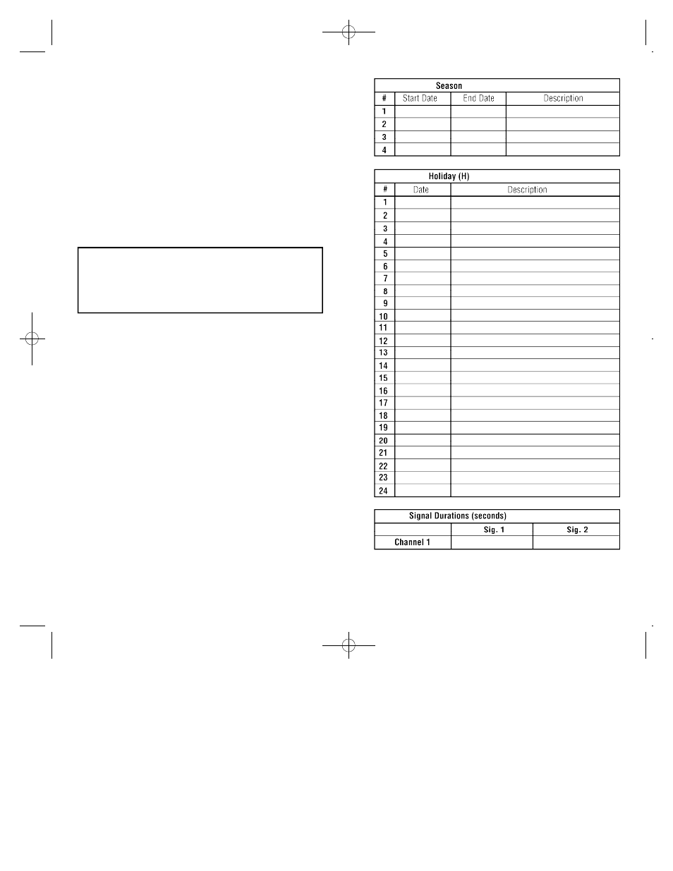
WE SUGGEST YOU MAKE COPIES OF THE SCHED-
ULE SHEETS LOCATED IN BACK OF THIS BOOKLET
AND COMPLETE THEM PRIOR TO SETTING THE
UNIT.
2
Disconnect power at main panel prior to installing or
servicing this time switch or the equipment connected
to it. Connect in accordance with national and local
electrical codes. Installation by a licensed electrical
contractor is recommended.
DTS100B - DZS100BP 3/8/07 9:26 AM Page 7