NOSHOK 627 Series Pressure & Level Transmitters User Manual
Page 2
FMRC 3600, 3610, 3611, 3810 (including
supplement #1), ISA-S12.0. 01, IEC 60529 (including
amendment #1)
Installation and Commissioning
Model 625 pressure transmitter is connected to
the pressure source using the the threaded stainless
steel pressure port. Several pressure port sizes are avail-
able.
Model 626 pressure transmitter incorporates a stain-
less steel (or optional material) diaphragm at the end of
the pressure connection, providing a flush diaphragm
configuration. It is connected to the pressure source
General
NOSHOK Model 625, 626 and 627 transmitters are
approved for use in hazardous location applications as
follows:
Intrinsically Safe, entity approval for Class I, II and III,
Division 1, Groups A, B, C, D, E, F and G; and Class I Zone
0 Aex ia IIC
Dust Ignition-proof for Class II and III, Division 1,
Groups E, F and G
Non incendive for Class I, Division 2, Groups A, B, C
and D
using the G1/2 B or G1 B threads directly or through the
use of the available weld on adapters. Model 627 is a
submersible level transmitter and is suspended by the
attached cable in a tank. The hydrostatic pressure
produced by the liquid rising above the location of the
level transmitter is directly related to the actual liquid
level. Unless the metal body of the model 627 is
grounded directly in the mounting of the transmitter,
the drain wire in the cable needs to be grounded to a
suitable system ground. It is essential to do this for the
built in noise protection to be effective.
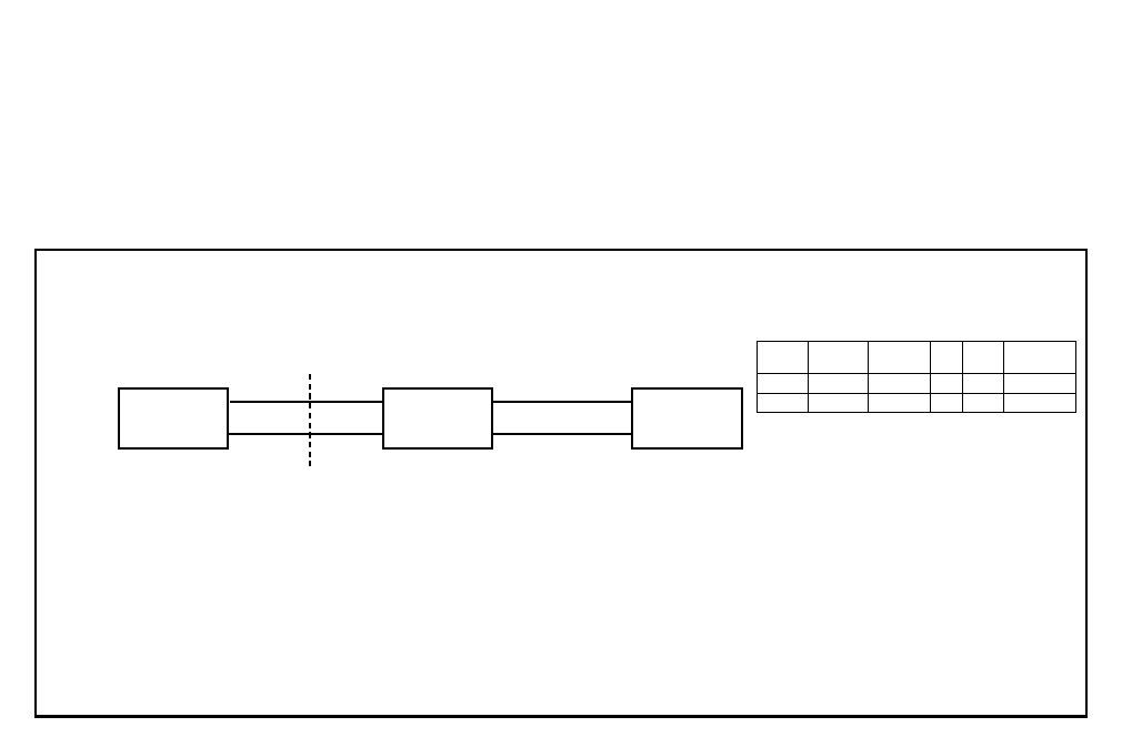
ENTITY PARAMETERS:
Vmax = 30 V, 1max = 100 mA, P1 = 1 W
Ci = 22 nF (FLYING LEADS: + 0.2 nF/m). Li = 0.1 mH (FLYING LEADS: + 2 nH/m)
NOTES:
1. THE INTRINSIC SAFETY ENTITY CONCEPT ALLOWS THE INTERCONNECTION OF TWO FM APPROVED INTRINSICALLY SAFE DEVICES WITH ENTITY PARAMETERS
NOT SPECIFICALLY EXAMINED IN COMBINATION AS A SYSTEM WHEN: Uo OR Voc OR V1 ≤ Vmax, 1o OR 1sc OR 1t ≤ 1max, Ca OR Co ≥ C; + Ccable, La OR Lo ≥ Li + Lcable, Po ≤ Pi
2. DUST-TIGHT CONDUIT SEAL MUST BE USED WHEN INSTALLED IN CLASS II AND CLASS III ENVIRONMENTS
3. CONTROL EQUIPMENT CONNECTED TO THE ASSOCIATED APPARATUS MUST NOT USE OR GENERATE MORE THAN 250 Vrms OR Vdc
4. INSTALLATION SHOULD BE IN ACCORDANCE WITH ANSI / ISA RP12.6 ″ INSTALLATION OF INTRINSICALLY SAFE SYSTEMS FOR HAZARDOUS (CLASSIFIED) LOCATIONS AND THE NATIONAL ELECTRICAL CODE θ
(ANS 1 / NFPA70) SECTIONS 504 AND 505
5. THE CONFIGURATION OF ASSOCIATED APPARATUS MUST BE FACTORY MUTUAL APPROVED UNDER ENTITY CONCEPT
6. ASSOCIATED APPARATUS MANUFACTURER’S INSTALLATION DRAWING MUST BE FOLLOWED WHEN INSTALLING THIS EQUIPMENT
7. THE 625, 626, 627 SERIES ARE APPROVED FOR CLASS I, ZONE 0 APPLICATIONS. IF CONNECTING AE x [ib] ASSOCIATED APPARATUS OR AEx ib I.S. APPARATUS TO THE 625, 626 AND 627 SERIES THE
I.S CIRCUIT IS ONLY SUITABLE FOR CLASS I, ZONE I OR CLASS I, ZONE 2 AND IS NOT SUITABLE FOR CLASS I, ZONE 0 OR CLASS I, DIVISION I HAZARDOUS (CLASSIFIED) LOCATIONS
8. NO REVISION TO DRAWING WITHOUT PRIOR FACTORY MUTUAL RESEARCH APPROVAL
Internal
Hirschmann
Cable
M12
Bendix Junction Box
+Supply
1
Red/Brown
1
A
1
+Output
2
Black/Green
3
B
2
4 mA to 20 mA 2-WIRE SYSTEM
NON-HAZARDOUS LOCATION
HAZARDOUS (CLASSIFIED) LOCATION
CLASS I, ZONE O, GROUP IIC
CLASS I, DIVISION I, GROUPS A, B, C, AND D
CLASS I, DIVISION I, GROUPS E, F AND G
CLASS I
(NOTE 2)
625, 626 and 627 SERIES
ASSOCIATED APPARATUS
CONTROL EQUIPMENT
(NOTE 5)
(NOTE 6)
(NOTE 7)
(NOTE 3)