Martel Electronics BetaGauge 321A User Manual
Page 7
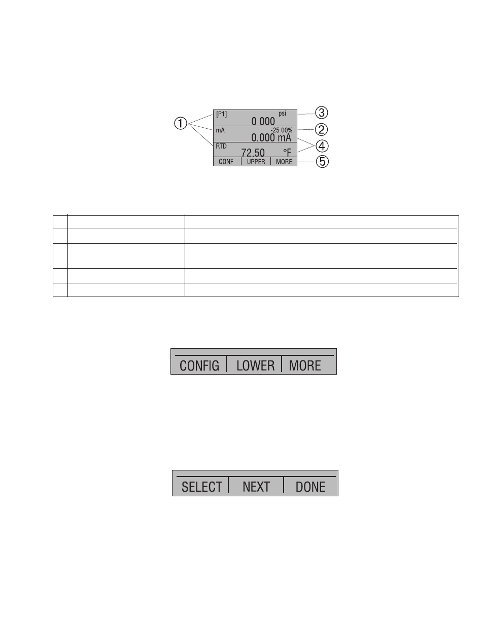
2.1 Calibrator Display
The Calibrator Display consists of two regions: The menu bar (located along the bottom
of the screen) is used to access a menu system. The main display (the rest) consists of
up to three process measurement sub-regions. These sub-regions will henceforth be
referred to as the UPPER, MIDDLE and LOWER displays. Figure 3 shows the location of
the different display fields while table 3 describes them.
Figure 3
Display
Table 3 Display Functions
No. Name
Description
1
Primary Parameters
Indicates what is being measured.
2
Span Indicator
Indicates the percent of the 4 to 20 mA span. (For mA and
mA Loop functions only)
3
Pressure Units
Indicates one of 17 pressure units available for display.
4
Units
Indicates the unit of measure for the display.
2.1.1 Main Menu Functionality
There are three options on the Main Menu, CONFIG, {current display} and MORE. The
Main Menu is home for the menu display.
2.1.1.1 Setting the Current Display
The current display is indicated by the center option on the Main Menu, pressing the F2
key will toggle the current display.
2.1.1.2 Setting Current Display Parameters
To set the parameters of the current display use the CONFIG option to get to the Display
Configuration Menu.
Here the SELECT option will toggle through the choices for each parameter. The first
parameter is MODE. Since voltage, current and switch test modes all use the same
jacks, two of these functions cannot be used concurrently. The ability to select certain
functions is limited based on what is already selected in another active display. The
NEXT option is used to change to the second parameter. Only RTD and Pressure modes
have a second parameter, RTDs can be read in Celsius or Fahrenheit and Pressures can
be read in 11 engineering units.
5