1 calibration of the output level – Anritsu AWGN MU368060A User Manual
Page 28
Section 5 Sample Calibration
5-2
5.1 Calibration of the Output Level
5.1.1 Adjusting the output level for the signal generator
Calibration of the output level at the RF connector terminal for the signal
generator is explained here.
A sample power setting with a 7.68 MHz noise signal bandwidth and –20
dBm/3.84 MHz at the RF output connector terminal is shown below.
(1) Set the following parameters for this unit.
Digital Mod
: On
System
: Noise1
Noise Bandwidth
: 7.68 MHz
Calculate Bandwidth : 3.84 MHz
(2) Calculate the total noise power for –20 dBm/3.84 MHz.
Read the Calculated Level on the display. With the parameter set in
Step (1), this value should be –3.45 dBm. Figure out the total noise
power using the formula below:
Total power = –20 dBm – (–3.45 dB) = –16.55 dBm
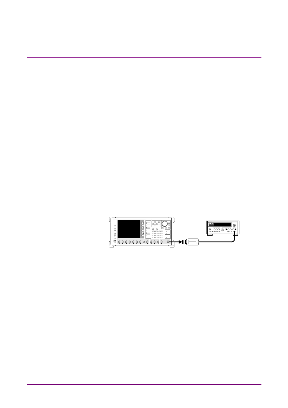
(3) Connect the power meter to the RF output connector for this unit.
(4) Set the output level for this unit so that the indication value of the
power meter becomes the total power found in Step (2). This com-
pletes calibration to the –20 dBm/3.84 MHz noise level at the RF
output connector terminal.
Consider the level accuracy for the setting of this calibration method. It
is figured out by the following formula:
Level accuracy
= Band calculated accuracy (Calculated Level accuracy) + power me-
ter accuracy
= ±0.6 dB (when the noise band is 7.68 MHz) + power meter accu-
racy
Anritsu
Mキ3681A
Anritsu
POWER METER ML4803A