6hwxs 4.1 switching status, 2 switching point, 3 functions chart – KROHNE LS 4100 EN User Manual
Page 14
LS 4100/LS 4150
03/2002
14
6HWXS
4.1 Switching
status
The switching status can be checked with closed instrument by means of the illuminated ring in
the upper part of the housing.
By interchanging of the connection cables, you can modify the switching status of the transistor
output (T). For the electronics version contactless electronic switch (C) you have to use a jumper
in the plug between terminal 2 and 3 to modify the switching status. You can adjust the requested
mode acc. to "4.3 Functions chart" (see "3.2 wiring plan").
A = max. detection or overfill protection,
B = min. detection or dry run protection.
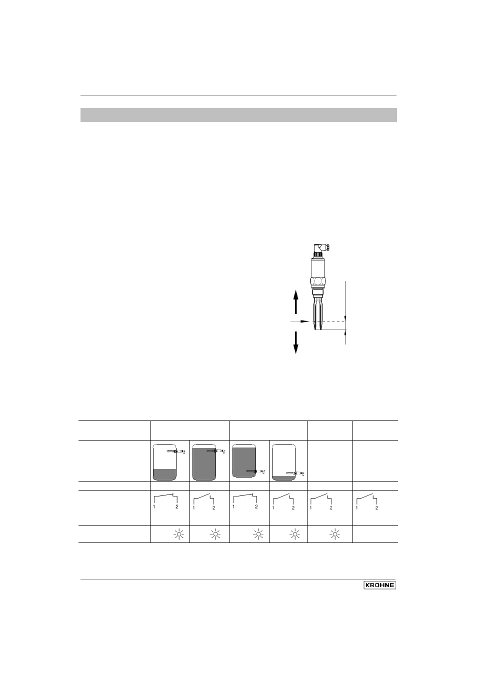
4.2 Switching
point
The switching point of LS 4100/LS 4150 is
preadjusted and does not require further
modifications.
The statements on the position of the switching
point (see also "2.1 Mounting instructions")
relate to water (density 1.0 g/cm
3
). For mediums
with a different density, this switching point
shifts, depending on the density and the
installation, in the direction of the housing or
tuning fork tip.
A density change of 0.1 g/cm
3
results in a
shifting of the switching point by approx.
2.5 mm.
4.3 Functions
chart
The following chart provides an overview of the switching conditions dependent on the ad-justed
mode and level. To set the mode, please read the information in "3.2 Wiring plan".
Mode A
Mode B
Response
of the fault
monitoring
Failure of the
supply voltage
Level
individual individual
Transistor (T) conducts
blocks
conducts
blocks
blocks
blocks
Contactless electrical
switch (C)
Switch
closed
Switch
open
Switch
closed
Switch
open
Switch
open
Switch
open
Signal lamp
green
red
green
red
red
{
Switching point with
lower density
Switching point
with higher density
Switching point
25 mm
Fig. 4.1